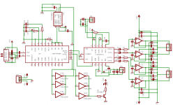
I am designing a balanced output AL1201G based DAC from wavefront.
The DAC will take S/PDIF in, and uses the CS8414 receiver. The output is provided by 4 single opamps, and there is an auto reset function provided by a TLC7705 and SN74HC04. When there is no signal lock the voltage supervisor resets the receiver repeatedly until the signal is locked.
The digial and analog GND planes are seperate and there is a leaded ferrite bead between them.
Does it look sane? This is my very first attempt at a DAC so any advice is welcome.
I am especially looking for input around the CS8414 and the AL1201G.
Attachments
hayenc said:I would be curious to know reasons for selecting the AL1201G over other choices, such as the Wolfson 8740. I could not find much in any threads other than the Burr Brown chips.
I am not familiar with that part, but my part choices here are based partly on input from a couple "recording biz" engineers I know here in Nashville who really like the AL1201. Also I chose it because it is SOIC which is as small as I want to go, no SSOP for me. (well not yet anyway)
")
The AL1201 is also very easy to use. And since this is my first run at a DAC I want something extremely hard to muck up.
Cheers!
Russ
Ah! Russ! You are beating to me to the punch on producing a balanced output DAC, a project I have been slowly tinkering with for some time without getting far enough to have anything worth posting. Your approach looks very appealing, I was getting led astray by overthinking and overdesigning the power feeds and clocking arrangements.
Last question: When do you find time to sleep?
Cheers, Terry
Last question: When do you find time to sleep?
Cheers, Terry
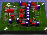
Only advice I would have is to change some of the routing (it's obvious from even the EAGLE3D pic). The FILT pin is very sensitive and should have very short traces to the filter caps/resistors (i.e. use SMD parts in this case). Also, the corresponding VA+ and AGND pins should also have decoupling as close as possible i.e. use SMD if possible.
Hmmm.... since you think ahead, can you think of presizing the board to slide into a small case?
Like Parts Express "heat sink box"
Like Parts Express "heat sink box"
3.4" seems right (assuming the narrowest part of the wall is 1/16"), but i can't find any measurements on either the parts express or penn fabrication sites. if parts express can't provide that information on the phone or in email, someone may have to sacrifice $8 to discover the truth.
Russ White said:Hmm thats a nice little case, what width would it take to get it to slide in? It seems from the manufacturers site that the ouside width is 3.54" So would it be like 3.4" PCB width? Hard for me tell... Anyone know?
Sorry, thought there was a data sheet. I have one and will measure it in the next few days. I did a project for it, cut a perfboard to fit, epoxied the edges and filed and sanded the epoxy to make it smooth, it would have been good to know the inner dimensions first.
One concern is having room for two XLR's and the coax/phono for digital. Might be tight on the PE box.
If you check my project link you will see that it is no problem to fit 2 XLRs and a coax/phono. I successfully fit a ton of connectors on this box, including WBT phono's which are larger than the typical connector.
The only disadvantages of this box are - (a) the end plates are steel so its harder to drill them, (b) the aluminum box needs to be tapped and threaded for screws to hold the end plates (c) the box top/bottom does not come apart, you need to slide the board in, but you knew that.
I think the box looks great by the way.
Don't ask me why the end plates are steel and the box is aluminum, but they do match up.
joster said:Will the power supply fit in there as well? Or will that be external?
I actually think I can make it fit for the 8" case.
Box Size
OK, time to test your vernier skills.
This is a pic measuring the board inside the box. By my read the board is 8.498 cm wide. It fits with some room to spare. Board width measurement
Here is an inside measurement of the box itself. By my read its 8.505 cm wide, but I've got a better view of the original calipers than is shown in the pic.
Box Inner dimension measurement.
How is the design coming?
Thanks for the data!
The design is comi g along very well. I am just switching some parts around (mostly making passives SMTs).
Also using a dual NOT gate instead of what I had as I only need two.
But all in all the circuit is nearly complete. I ordered some of the DAC chips last week. They should be here tomorrow.
I am hoping to get some prototype PCBs made in the next couple weeks.
Also I am making some decissions about the power suppy, and th use of PCB mounted trafo. I think I will use use two PCBs both designed to mount flush at both ends of the box.
Also I am looking at other similar eclosures just to see what will be the best/easiest chasis to use.
The DAC PCB will be designed for both optical S/PDIF(TORX) as well as standard S/PDIF.
Cheers!
Russ
- Status
- This old topic is closed. If you want to reopen this topic, contact a moderator using the "Report Post" button.
- Home
- Source & Line
- Digital Source
- AL1201G based DAC - looking for input