I found an old circuit card in the recycling.
It has 16 pieces of 2N4092 JFET transistors.
They are in TO-18 Case. Data is not too bad.
I will match some pairs for differential input to build a ClassA power amp.
TO-18, 2N4092 N-JFET, Data
VDS 40 V
Power 0.360 W
IDSS 15 mA min
RDSon 50 Ohm
Ciss 16 pF
T-rise 20 ns
For the VAS I will use BC639/640 TO-92.
They are 1 Watt and I can use more current in VAS-stage.
I plan to use 5+5mA in input stage.
And 25mA in VAS stage.
These two stages will be powered at regulated +-20 Volt.
From a small 2x18VAC transformer.
Ouput will use unregulated power supply.
Push-Pull at bias ~1.5-2.0 Ampere.
From 2x12VAC transformer.
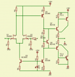
Here is the basic default circuit idea.
Version:
ClassA-JFET_1.0
It has 16 pieces of 2N4092 JFET transistors.
They are in TO-18 Case. Data is not too bad.
I will match some pairs for differential input to build a ClassA power amp.
TO-18, 2N4092 N-JFET, Data
VDS 40 V
Power 0.360 W
IDSS 15 mA min
RDSon 50 Ohm
Ciss 16 pF
T-rise 20 ns
For the VAS I will use BC639/640 TO-92.
They are 1 Watt and I can use more current in VAS-stage.
I plan to use 5+5mA in input stage.
And 25mA in VAS stage.
These two stages will be powered at regulated +-20 Volt.
From a small 2x18VAC transformer.
Ouput will use unregulated power supply.
Push-Pull at bias ~1.5-2.0 Ampere.
From 2x12VAC transformer.
Here is the basic default circuit idea.
Version:
ClassA-JFET_1.0
Attachments
BC639/640 come into a TO-92 package and have more than 200ºK/W thermal resistance from junction to ambient. This means that the temperature of the junction will rise 200ºC for each watt dissipated in the device, so 25mA*20V make 0.5W and 100ºC temperature rise... This is quite an insane working point.
Use BD139/140 instead, the die is the same as for BC639/640 but they come into a more convenient TO-126 package with 100ºK/W Rth-ja, and they are easy to attach to a heatsink if required.
Use BD139/140 instead, the die is the same as for BC639/640 but they come into a more convenient TO-126 package with 100ºK/W Rth-ja, and they are easy to attach to a heatsink if required.
lineup said:I found an old circuit card in the recycling.
Hi Lineup, open to some suggestions?
")
If it was me , I will do the following :
- Add a 1k resistor in series with the input, without it , if you use a pot at the input ( a good idea ) , it will certainly oscillate at the minimum volume position and even using a preamp this resistor increase stability.
- Add a resistor with same value of R4 in the other drain of the LTP , that way the Miller capacitance of both Fets of the LTP will become similar.
- Add a resistor in series between the collector of Q3 (CCS) and the sources of the Fets , this resistor help to isolate the LTP sources from the non linear output capacity of Q3.
- I will change the LEDs for two diodes, contrary to same people here, I prefer a CCS with to diodes (1N 4148) as references , I find the LEDs more noisy.
- Using the Leds or two diodes I will put a 100 uF capacitor across them.
-Add a capacitor across the VBE transistor Q8 , that way the base of the drivers will see the same signal.
This is what I would do...if I were a rich man....
- Status
- This old topic is closed. If you want to reopen this topic, contact a moderator using the "Report Post" button.