Dear Sirs,
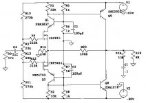
searching the web for info on simple amps schematics using darlingtons I found the schematic I am attaching.
It is so simple that I even wonder if it could work!
Nevertheless I find it intriguing.
I would like to hear some comments on it.
Thank you so much.
Kind regards,
bg
searching the web for info on simple amps schematics using darlingtons I found the schematic I am attaching.
It is so simple that I even wonder if it could work!
Nevertheless I find it intriguing.
I would like to hear some comments on it.
Thank you so much.
Kind regards,
bg
Attachments

Let's refer my post there:
http://www.diyaudio.com/forums/showthread.php?s=&postid=781797#post781797
Regards,
http://www.diyaudio.com/forums/showthread.php?s=&postid=781797#post781797
Regards,
edl said:Let's refer my post there:
http://www.diyaudio.com/forums/showthread.php?s=&postid=781797#post781797
Regards,
Dear Sir,
thank you greatly for your extremely kind and valuable reply.
So this kind of circuit do not intrigue only me !
I find it even exciting.
Tell me please, have you built your circuit?
How does it sound?
I am sure its potential is very great indeed.
As I am not so sure that to sound good an amp must be complex!
In the next days I will study your thread in depth.
Any your advice would be extremely welcome, appreciated and valuable to me.
Thank you so much again.
Kind regards,
beppe
Hi beppe
I have built this amp a while back, it isn't one of the baddest sounding amplifiers out there. I would recommend it. It's very cheap to build and uses common parts. I have done some modifications to the circuit to improve on quality and boosted the power output. I'll have to look where I put the circuit, then I'll post it here.
I haven't been on diyaudio for some time, but I'm glad to be back!")
Cheers,
Werner
I have built this amp a while back, it isn't one of the baddest sounding amplifiers out there. I would recommend it. It's very cheap to build and uses common parts. I have done some modifications to the circuit to improve on quality and boosted the power output. I'll have to look where I put the circuit, then I'll post it here.
I haven't been on diyaudio for some time, but I'm glad to be back!
Cheers,
Werner
beppe61 said:It is so simple that I even wonder if it could work!
Nevertheless I find it intriguing.
I would like to hear some comments on it.
An externally hosted image should be here but it was not working when we last tested it.
Yes, it is simple.
I am not sure it is really Hi-Fi.
But I think it will work.
Here is many Solid State Power Amplifier Schematics
For example:
This very interesting and original 100W 2SC2922 2SA1216 Amplifier
See my attachment.
Attachments
sousmielie said:Hi beppe
I have built this amp a while back, it isn't one of the baddest sounding amplifiers out there. I would recommend it.
It's very cheap to build and uses common parts.
I have done some modifications to the circuit to improve on quality and boosted the power output.
I'll have to look where I put the circuit, then I'll post it here.
I haven't been on diyaudio for some time, but I'm glad to be back!
Cheers,
Werner
Dear Sir,
thank you very much for your very interesting reply.
I am attaching (for me writing in English is not the easiest thing) some words I wrote in another similar thread regarding topologies using darlingtons.
------
I would like to explain my interest for simple amps using just a single pair of darlington in the output stage.
During the last 6 months I have tried a number of integrateds and power amps in my system to drive a quite demanding pair of Dynaudio speakers.
Most failed to give an adequate bass response (i.e. fast, deep, powerful and damped).
The best power amp I listened in my system has been two English monos rated 45W/8ohm that I had the opportunity to open and see inside.
I could see in each mono:
1) a toroidal transfo made by ILP type:5322 S.N.:2102
2) two good sized filter caps
3) 7-8 small plastic case bjts (in TO92 case I think)
4) a single pair of TIP146/TIP141 per channel.
This has been by a long margin the best amp I tried in my sistem.
On this basis I am now very interested in very simple topologies.
My dream would be to find a kit of a power amp with just 4-5 bjts that could be used along with the output pair of point 4).
This kit with a very powerful power supply could have the potential to sound very good IMHO.
The sound of the monos pair I mention it is very good even with demanding speakers.
The monos have been circulated among a number of audio friends of mine.
Every time the judgement has been positive to say the least.
If I were good at cloning that woudl be my target.
As I said I will study all the minimalist designs I will find that could be used with a single darlington output pair.
-----
So I will be waiting any your kind and precious further information.
Thank you very much again for your very valuable advice
Kind regards,
beppe
Re: Re: Kind request of opinion - minimal schema with darlingtons.
Dear Sir,
thank you sincerely for your kind and helpful reply.
1) Did you build it? I feel that you are not very optimistic about the resulting sound. Am I wrong?
2) Thank you very much for the link.
I found it today along with the schematic googling for "TIP142".
3) Very interesting indeed. Excellent Sanken output stage and very basic circuit as well.
Did you build it? How about its sound? Do you think it would be miles better than the darlingtons circuit?
As I wrote above I found a truly great sounding amp with just a single pair of darlington at the output.
Ok. The whole circuit is quite more complex, with about other 9 bjts (4 BC556, 4 BC546 and 1 BC555) besides the output pair (tip146/tip141).
So I became interested in circuits using darlingtons.
Thank you very much indeed.
Kind regards,
beppe
Originally posted by lineup
1) Yes, it is simple. I am not sure it is really Hi-Fi.
But I think it will work.
2) Here is many Solid State Power Amplifier Schematics
For example:
3) This very interesting and original 100W 2SC2922 2SA1216 Amplifier
See my attachment.
Dear Sir,
thank you sincerely for your kind and helpful reply.
1) Did you build it? I feel that you are not very optimistic about the resulting sound. Am I wrong?
2) Thank you very much for the link.
I found it today along with the schematic googling for "TIP142".
3) Very interesting indeed. Excellent Sanken output stage and very basic circuit as well.
Did you build it? How about its sound? Do you think it would be miles better than the darlingtons circuit?
As I wrote above I found a truly great sounding amp with just a single pair of darlington at the output.
Ok. The whole circuit is quite more complex, with about other 9 bjts (4 BC556, 4 BC546 and 1 BC555) besides the output pair (tip146/tip141).
So I became interested in circuits using darlingtons.
Thank you very much indeed.
Kind regards,
beppe
ilimzn said:Yes, very interesting and very thermally unstable original amplifier
Thank you Sir.
This is unfortunate.
It was too good to be true, or as someone say too simple to be good.
Why life has always to be complicated ?
It is a real pity.
Are you aware of any system to make it more stable?
Thank you very much indeed.
Kind regards,
beppe
Yes, Beppe, the bias network for the MOSFETs on the input has to be made in such a way to have a negative temperature co-efficient, i.e. not with ordinary resistors, other measures would involve putting a low value resistor in the emitter of each output BJT (altough there is a tradeoff involved here, regarding damping factor). The simple amp in that schematic has another problem, which is hum induction into the input due to the way the MOSFETs are biassed from the power supply, but this could be cured with a few caps. Cascoding could be greatly improved by connecting the caps to the common point of the input MOSFET sources, this would make the nonlinear Cgd of the MOSFET dissapear and the distortion drop by removing the mechanism that introduces it, rather than trying to correct it via NFB.
The circuit reminds me very much of Jean Hiraga and all the above being said, it's not a bad idea at all, just needs some work into making it a real world amp.
The circuit reminds me very much of Jean Hiraga
and all the above being said, it's not a bad idea at all, just needs some work into making it a real world amp.ilimzn said:Yes, Beppe, the bias network for the MOSFETs on the input has to be made in such a way to have a negative temperature co-efficient, i.e. not with ordinary resistors, other measures would involve putting a low value resistor in the emitter of each output BJT (altough there is a tradeoff involved here, regarding damping factor). The simple amp in that schematic has another problem, which is hum induction into the input due to the way the MOSFETs are biassed from the power supply, but this could be cured with a few caps. Cascoding could be greatly improved by connecting the caps to the common point of the input MOSFET sources, this would make the nonlinear Cgd of the MOSFET dissapear and the distortion drop by removing the mechanism that introduces it, rather than trying to correct it via NFB.
The circuit reminds me very much of Jean Hiraga
Thank you very much Sir.
So it is very far from a "ready to use" schematic.
What is your opinion on the minimalist darlington schematic?
Thanks a lot.
Regards,
beppe
Darlington Transistors are not very often used in amps.
They are most often not made for audio use.
But, most power amplifiers use Transistors in darlington configuration.
In the output stage.
By using two or more separate transistors it is possible get a better amplifier.
You can make darlington output stage from good 'audio' transistors you want to use.
Figure 5.20:
- a) The Darlington connection of two transistors to obtain higher current gain and
- b) the Sziklai connection of an NPN and PNP transistor to obtain the equivalent of a high-current-gain NPN.
Darlington and Sziklai Connections
They are most often not made for audio use.
But, most power amplifiers use Transistors in darlington configuration.
In the output stage.
By using two or more separate transistors it is possible get a better amplifier.
You can make darlington output stage from good 'audio' transistors you want to use.
An externally hosted image should be here but it was not working when we last tested it.
Figure 5.20:
- a) The Darlington connection of two transistors to obtain higher current gain and
- b) the Sziklai connection of an NPN and PNP transistor to obtain the equivalent of a high-current-gain NPN.
Darlington and Sziklai Connections
beppe61 said:
Thank you very much Sir.
So it is very far from a "ready to use" schematic.
What is your opinion on the minimalist darlington schematic?
Thanks a lot.
Regards,
beppe
beppe-
"ready for use",and pretty deeply covered here are JLH (PLH,too),but even Mini A or any other Aleph are not even slightly complicated amps for build;
at least -not comparing to few other amps which I make during the years.....
hehe-like I always say,I know what I know with tubes,but for SS -I'm good just for repairs,not for constructions...
in DIY oriented amp making,crucial (and most fun) aspect is time;don't hurry-if you don't understand something,just stop and try to figure out exactly that "something"; then do what you can do with more knowledge....and again-learn,build,learn, build.
complexity in some schematic often is not related with number of parts ,active or passive,whatever....
lineup said:Darlington Transistors are not very often used in amps.
They are most often not made for audio use.
But, most power amplifiers use Transistors in darlington configuration in the output stage.
By using two or more separate transistors it is possible get a better amplifier.
You can make darlington output stage from good 'audio' transistors you want to use.
Figure 5.20:
- a) The Darlington connection of two transistors to obtain higher current gain and
- b) the Sziklai connection of an NPN and PNP transistor to obtain the equivalent of a high-current-gain NPN.
Darlington and Sziklai Connections
Dear Sir,
thank you so much for your kind and valuable reply.
I thought that having the driver and the power transistor on the same chip were a smart solution (one chip instead of two).
But I can well understand your point: the choice is much wider with separate components.
Speaking of the Sziklai pair connection I am attaching another "intriguing" schematic, part of anold line stage preamp, that I liked very much is indeed a Sziklai pair, if I am not wrong.
I think that this schema accurately built and with a nice power supply could sound phenomenal, up to well regarded commercial solution.
I invited other DIYAUDIO friends to built it and report about their listening impressions.
No on accepted the invitation dismissing the preamp right away.
I have a very basic set-up so I would have liked to get some confirmations by people much more expert that me.
I go on with thinking that this schema is exceptionally simple nevertheless quite good sounding.
And, as I said, I think it can be classified as a Sziklai pair.
Bjts are BC107 and BC303 while the supply is a single 0-60V.
Thank you very much again.
Kind regards,
beppe
Attachments
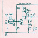
That is good preamp, beppe61.
People do not think simple can be good. But they are wrong!
I have built such preamp and used them.
But nobody is interested.
Because they like Advanced and Complicated.
They think they get better result, but maybe only get more problems.
The more parts - the more possible troubles.
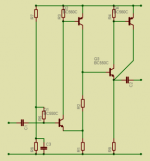
Here is my version of your amplifier.
Uses an output buffer stage of 2 transistors.
I have posted it 3-4 times, already ........
And here it is again:
People do not think simple can be good. But they are wrong!
I have built such preamp and used them.
But nobody is interested.
Because they like Advanced and Complicated.
They think they get better result, but maybe only get more problems.
The more parts - the more possible troubles.
Here is my version of your amplifier.
Uses an output buffer stage of 2 transistors.
I have posted it 3-4 times, already ........
And here it is again:
Attachments
beppe61 said:Thank you very much Sir.
So it is very far from a "ready to use" schematic.
Exactly - it would be very thermally unstable and it's a big question if it could survive longer than a few minutes to begin with. One problem is that the positive temperature coefficient of the input stage is also amplified by the input stage, and this in turn sets the bias current for the output stage, which itself has positive temperature coefficient. All in all, as this amp heats up (and it should be a class A design!) the bias current increases VERY quickly and will result in output stage failure.
I was actually intrigued by it so decided to do some simulations. Here are some conclusions:
1) The input MOSFETs are not well chosen, according to the models I have. IRF710 and IRF9610 appear to be much better, and IRFD110 and IRFD9120 are even better than that.
2) Output stage MUST have emitter resistors in order to even hope of making the whole amp temperature stable.
3) Modulating the cascode voltages reduces distortion by 30-50% in numbers, but more importantly, this improvement comes from lowering of high order harmonics, you end with a very nice decreasing spread of low order harmonics (h5 is already >100dB below fundamental).
4) Input stage benefits from source resistors, and increased stage current as this increases MOSFET gm and simultaneously makes it more linear. The down side is that each of the input stage transistors generates at least 0.5W of heat, so they need to be the type that can be heatsinked.
5) Output stage works best in class A (by a large margin!), because opel loop gain is low and so is feedback, too low to effectively compensate for class AB operation.
6) I have also tried a MOSFET output version which is FAR easyer to thermally stabilize, and in fact shows more promise. It does have somewhat higher distortion, as well as output impedance. In either case the distortion increases less than 2x from 1 to 10kHz, and the harmonic spread remains the same. The figures are not stellar (0.15% at 10kHz, 20W into 8 ohms) but the open loop gain is low and so is the feedback factor - and the harmonic spread promises a pleasant sound. The MOSFET version has VERY high bandwidth, the BJT version is not far behind.
I don't have the schematic at hand here, but will try a few more sims with bipolars as well, before I post something. Just keep in mind it has not been built, just simms nicely.
What is your opinion on the minimalist darlington schematic?
Thanks a lot.
Regards,
beppe
I think I built something very similar to it a long time ago, and it worked fine, but it was too far in the past for me to recall how it sounded.
I did once build a version of the Quad 405 amp with darlingtons on the output (MJ11015/11016) which works fine, but it has been put into biamped LF service for the last 10 years or so. It's driving a 4 ohm load with a single pair, which, to be honest, looking at the SOA ratings for these transistors, is highly optimistic - even so, the SOA ratings must be very pessimistic because this amp has been completely reliable, even though it's now some 15 years old. SOA ratings of most Darlington BJT packages are nothing to write home about, unfortunately.
yes i have no doubt this will work however the bias will be wrong
to low i think and it will a suffer fom xover distortion i would have liked to see a capacitor around a 100 pf between the collctor and base of the driver transistor but dont expect to much from this a the diff pair on the input does not seem to have a smooth current source but we all have to start some where
to low i think and it will a suffer fom xover distortion i would have liked to see a capacitor around a 100 pf between the collctor and base of the driver transistor but dont expect to much from this a the diff pair on the input does not seem to have a smooth current source but we all have to start some where
Beppe, I have sent you a message through the forum message system. I was just wondering if you had received it. You should see the message in the email account that is registered with the forum. If you have not received it please let me know and I will try to resend or use other means.
richie00boy said:Beppe,
I have sent you a message through the forum message system.
I was just wondering if you had received it.
You should see the message in the email account that is registered with the forum.
If you have not received it please let me know and I will try to resend or use other means.
The e-mail address is that of my office.
Tomorrow I will check.
Thank you very much
Regards,
beppe
- Status
- This old topic is closed. If you want to reopen this topic, contact a moderator using the "Report Post" button.
- Home
- Amplifiers
- Solid State
- Kind request of opinion - minimal schema with darlingtons.