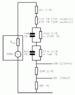
This is my passive RIAA network for testing mm preamps with nominal 47K input. It has an attenuation of 38dB at 1 KHz so it can be fed direct from a cd player. Nominal accuracy is +/- 0.2 dB to 20 KHz.
Output impedance is low enough not to be affected by any cartridge loading capacitors
Output impedance is low enough not to be affected by any cartridge loading capacitors
Attachments
A few points. Most CD players have an output resistance of a few hundred Ohms and that will affect your response. Your graph seems to indicate errors larger than 0.2dB, but you have the figures. Even so, 0.2dB error is quite large for a design error - let alone once the effects of component tolerance are factored in. Loading capacitance on any inverse RIAA network will effect HF response. Once it exceeds 200pF or so, you will see errors begin to creep in.
This network has a design error of <0.01dB DC to 100kHz (includes 3.18us) and the worst possible combination of component tolerances produces an error <0.1dB.
This network has a design error of <0.01dB DC to 100kHz (includes 3.18us) and the worst possible combination of component tolerances produces an error <0.1dB.
Attachments
A couple of hundred ohms output impedance won't have any effect in the audio band.
I tried adding 220pF on the output to represent the higher end of typical cartridge loading and it has negligible effect below 20KHz.
I wanted a reasonably accurate design using common component values that were readily available in 1% tolerance.
Your circuit is suitable as a laboratory standard but the values won't be so easy for hobbyists to get.
davidsrsb said:Simulating EC8010s circuit, it's ruler flat until it roles off with -0.6dB at 20 KHz and -3dB at 50KHz
That's right, it's -3dB at 50kHz to emulate the 3.18us roll-off included in Neumann cutting lathes that protects the cutting head.
davidsrsb said:Your circuit is suitable as a laboratory standard but the values won't be so easy for hobbyists to get.
Yes, but it's small enough to use several series/parallel components to get the required valus, with very little extra cost.
EC, I note your circuit is optimised for 50/75 Ohm impedance. Do you have a version better suited for the normal 2/500 Ohm output of ordinary CD players?
davidsrsb said:
Your circuit is suitable as a laboratory standard but the values won't be so easy for hobbyists to get.
Mouser has them.
pinkmouse said:EC, I note your circuit is optimised for 50/75 Ohm impedance. Do you have a version better suited for the normal 2/500 Ohm output of ordinary CD players?
It's more that the total series resistance before the RC networks needs to be 2197 Ohms. If you knew the output resistance of your CD player, you could simply subtract it from that total value to find out what value of resistance to substitute.
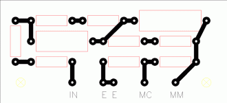
Oh, and to forstall your next question, here's the PCB layout I used...
Attachments
I have heard of the Neumann pole arguement, (mainly used to justify non-inverting amplifiers without the extra pole to keep roll off going). Was there much real signal much above 20KHz? I think MM cartridges are not going to have much output up there apart from distortion harmonics. I am a great believer in not amplifying rf signals needlessly with so much 25KHz plus around from ADSL and Internet over Powerline.
I normally use passive RIAA (which doesn't have the non-inverting amplifier problem). Also, I use an MC cartridge...
My justification for implementing 3.18us is that phase response is affected a decade away from a turnover point, so phase at 5kHz is affected by the 50kHz zero. I take your point about all the muck past 20kHz, though.
There's another argument for implementing 3.18us in inverse RIAA, and that is that the passive network can't keep HF rising indefinitely (I'm sure you realised this). You have to trade HF against 1kHz loss. If we have to do that anyway, why not make the failing a virtue and match it to the Neumann head?
The newer warp filter is not used at the recording stage, it is only recommended for playback.
In my view the IEC version and some with slightly extended bass response ruin a major attribute of vinyl playback. Avoid it if possible and mimic the old style curve.
Your inverse RIAA should be based on the recording curve and since you plan to use it for tesing other RIAA stages I suggest you aim for an accuracy about 10 times better than the prototype circuits. At least then you will know with a reasonable certainty that errors are in the prototype and not in the reference.
This will require resistors to about 0.1% and caps about 0.5% (absolute not just matching accuracy) or better if you can achieve it (I don't know how), but I'm all ears.
Do your best to keep it very accurate. You are only building it once and only one channel.
By the way you can achieve tiny corrections by paralleling resistors many decades apart. The bigger one then does not need to be precision, 1% will do.
I am using modified inverse RIAA net
for the simulations...
note:
only two RIAA networks are show normal results
1. Morgan Jones all in one network
2. LC network by western electric
the zip file is too long...
here is web address if it is still on line...
http://www.siteswithstyle.com/VoltSecond/index.html
cheers
for the simulations...
note:
only two RIAA networks are show normal results
1. Morgan Jones all in one network
2. LC network by western electric
the zip file is too long...
here is web address if it is still on line...
http://www.siteswithstyle.com/VoltSecond/index.html
cheers
- Status
- This old topic is closed. If you want to reopen this topic, contact a moderator using the "Report Post" button.
- Home
- Source & Line
- Analogue Source
- Inverse RIAA