Do I have any volunteers for a mathcad sim of a t-line for the Tangband W5-1138SG using two drivers.
TSPs here
I understand the basics of esentially making it one quarter wave of Fs but I have seen lots of designs that do not use this simple formula and I do not fully grasp what the advantages and disadvantages of deviating from that formula are.
TSPs here
I understand the basics of esentially making it one quarter wave of Fs but I have seen lots of designs that do not use this simple formula and I do not fully grasp what the advantages and disadvantages of deviating from that formula are.
If nobody else volunteers, I think I'll have time later tonight.
Were you planning on a straight TL, or a Mass Loaded Transmission Line, (MLTL)?
Also, where you planning on
A) Hooking them up in parallel, to make a 2 ohm unit?
B) Hooking them up in series, to make an 8 ohm unit?
C) Hooking each up to separate amplifier? If that is what you are doing, and plan on crossing these subs over passively, what crossover point were you planning on using, and, (not necessary to answer) did you have an inductor coil size picked out? If so, what is the model number or the DCR of the coil.
The last two questions do not necessarily have to be answered, but would be nice to know.
Hi flae,
Quarter wave of Fs is a simple calculation for a very ideal and theoretical model. You must to consider the acoustical impedance of air or other filling material. This is why the efective lenght drops down to about +- 80% of theoretical lenght. Other parameters are important too, like T-S par, sectional areas of begining and closed/open terminus, straight or folded etc, etc
Quarter wave of Fs is a simple calculation for a very ideal and theoretical model. You must to consider the acoustical impedance of air or other filling material. This is why the efective lenght drops down to about +- 80% of theoretical lenght. Other parameters are important too, like T-S par, sectional areas of begining and closed/open terminus, straight or folded etc, etc
Sorry, flaevor.
I worked on it, and had something that looked kind of nice but it went bad somehow transferring from Sections to TQWT program.
To briefly summarize:
I assumed each speaker was driven by a separate amp or channel, so I kept the parameters the same except doubled the Vas and the Sd.
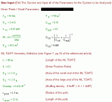
I came up with something like this:
Line length = 75 inches.
Area at top of line= 1 Sd.
Area at opening of line =0.3 Sd
Driver center to top, (closed end), of line = 25 inches
Stuffing density = 0.4
The response curve was not much different from a closed box of equal size, but the cone excursion was cut about in half.
Late here, will resume tomorrow with some graphs.
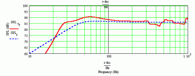
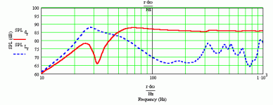
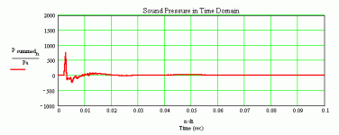
Well, what the heck. Here is some sims for a Mass Loaded Transmission Line. That is a transmission line with a port at the end. This is done in the TQWT worksheet.
It's a place to start, anyway.
Pretty good response for a subwoofer. Here are the parameters and setup for the box. Sorry about the units-that metiric stuff doesn't take over here, and certainly not at this time of the morning. Plenty of online calculators to help you convert.
Remember, the Vas and Sd are doubled in the user input section, because you are using two in the box. I am assuming you are connecting each driver up to a separate channel. Everything else is the same as Tangband's specs.
Attachments
wow!!! thanks a million. I had read an article about a mass loaded T-line and the interesting thing was that the bassreflex sim netted the same internal volume. So I took the interior dimensions of the cabinet I had in mind (not mass loaded but with two bends) and plugged them in to see what the bass reflex results would be and they were way less then ideal. Since I don't have mathcad and have never used the sheets I thought I'd see if you guys could help.
as far as the other details go...I had planned to put both speakers in the same line wired in series.
A german magazine often puts two drivers in one line, one at one third and the other at one fifth of the line(to minimize certain resonances). Then I remembered reading that the resonances occur independent of the placement in the line, or at least to some extent. So I figured why not place the speakers as close together as possible at the beginning of the line. I like the looks better.
In the end I was fishing for suggestions and your sims helped thanks again.
Flaevor:
Well, in this unit the driver position ratio is 0.5. which menas the centerline between the drivers is halfway down the length. Line position does affect the response, although somewhat less in a Mass Loaded TL than a standard TL.
I can redo the sim with both drivers in series. It won't change much, except that the sensitivity will be 3 dB less throughout the sim. I can alos rerun the standard TL I was talking about for you.
A couple of questions:
Are you crossing over passively, with inductors in the Line? Or are you planning to use a separate amp/crossover to run this sub?
And what frequency do you plan on crossing over?
Incidentally, a Mass Loaded TL does give somewhat different response from a bass reflex. The response an octave above cutoff is somewhat enhanced in a Mass Loaded TL.
I had planned on running them on a passive crossover probably crossing them at around 100-150Hz to a TB W4-xxx(model still undecided) and a tweeter also to be decided later.
I had considered using them with a plate amp, but they often have a 3-6 dB boost around 30Hz and I wasn't sure how to take this into acount.
Given that it's going to be a passiv design I could probably run them parallel and then do some king od impedence correction to the crossover.
What would you recommend. This is my first design that I'm trying to do from the ground up. My other speakers were a kit that I modified slightly for optical and price reasons.
One of the major design factors is size. It should be narrow not too tall and not to expensive, but still sound like something 2-3 times as expensive and large it all has to do with WAF and small european apartments.
Greets!
FYI, you can't just double Sd, Vas and get an accurate sim, so for separate amps/driver: double Sd, Vas, and halve Re, but not Le.
Just plugging the numbers in to get a ~0.707*Fs = 31.8 Hz Fb MLTL alignment, the lowest I recommend:
L = 51"
CSA = ~35.5" (recommend ~7.56" x 4.68")
zdriver = 16.5"
zport = 47"
density = 0.25 lbs/ft^3
rport = 1.5"
Lport = 11"
Ideally mount the drivers in a bipolar layout. Folded in half it wouldn't be all that big. If there's too much bottom end 'boom', roll it off with a more TL like response by damping the vent to suit.
Hmm, considering the XO point, might as well just stick the drivers at the end (zdriver = ~3") and get better floor loading.
FYI, if passive is used this low, there will be significant series resistance that will ruin this alignment. For instance, if the drivers are wired in parallel and a total series R = this new, lower resistance, then the response looks very similar to KW's.
GM
flaevor said:I had planned on running them on a passive crossover probably crossing them at around 100-150Hz to a TB W4-xxx(model still undecided) and a tweeter also to be decided later.
I had considered using them with a plate amp, but they often have a 3-6 dB boost around 30Hz and I wasn't sure how to take this into acount.
One of the things you must understand when building a system is that passive Xovers are very hard to do. To do them properly, you must download Speaker Workshop freeware or get some other program, get measuring equipment, and get ready to tear into it.
For this reason, most people use the crossover from an existing system. It could be from a manufacturer, it could be from someone else's project, whatever-they get a crossover that someone else has worked on and tweaked.
Whatever you do, don't just get a woofer/midbass, some quality tweeter, then hope someone will help you with the crossover. Nobody will be able to.
Since the crossover for a midbass to tweeter is around 2,000 Hz or so, it does not matter what size the box is. That is to say, if you see the midbass and tweeter you want in a small sealed studio monitor, but you want to make the box a different style or size, by all means do it. The crossover won't be affected-you can use it for your satellites.
My advice would be to build sealed satellites that go down to between 120 and 60 Hz, buy a plate amp and power your sub from that. Set your sub's crossover point for the region your satellites are 3 dB or 6 dB down, and then vary to taste. That is why plate amps for subs are so popular. This eliminates the necessity of making a passive crossover.
Buying a plate amp costs something, but passive components for a 120 Hz crossover also get expensive. And you can't vary the crossover point easily, like you can in a plate amp. And the inductor in the passive crossover will raise the Qts of the woofer, as well.
I don't know if you bought the Tangband five inch subs yet, but if yu haven't, here is an idea.
You might want to consider a single Tangband 8 incher. It is more efficient, moves more air and will give a bigger bass wallop than two five inchers. I gather it costs less than two five inchers as well.
Finally, if you do use a plate amp, plate amps normally work best with a four ohm speaker, which this 8 incher is.
Just a suggestion.
I'm well aware that passive crossovers are difficult. and to be honest I don't as of yet have sufficient knowledge to build a good one. I wanted to use one of the 4" TB drivers so as to enable a high crossover point to whatever tweeter I end up using. The TB subs (if you can call a 5" speaker a sub) were only going to take over the bottom end.
I could use an 8", but then it would likely wander over to the side of the enclosure in order to maitain the narrow footprint. Granted under 100Hz there are likely to be little if any phase problems but I had wanted to avoid this if possible purely for aesthetics. I think I mentioned already that this should end up being a high WAF (which means at our house: sounds good looks good didn't cost too much) box. 6"s might be an option. TB offeres a couple of those that also look interesting.
This is a test for me, an experiment to pass the time I don't have.
Sorry, i'm feel like a intruder........BUT
FYI, LT's work well with High BL and SPL factors, it means low Qts too. My actual project ( only a prototipe without finishing ) is something like it using tri eight inch where one is a sub driver in LT Schema. see some pictures here:
http://fotos.terra.com.br/album.cgi/*741146
Equalizing ways and matching fase of a passive crossover with tri ways , high power and low crossover points are a nithmare for everyone. Tomorrow you will see low power amps intermodulate trying to play some like hard charge, I'm seeing it today.
My sugestion is a woofer with low Qts, Fs, Le . High possible Spl and power intead of subwoofers. Otherwise a active crossover and bi-amp is a good choice for solving bass problems.
Enjoy
so the previous suggestion never came into being,... but I am looking at something similar for 2 w6-1139sg's in a ML tapered t-line. The reason behind the configuration is the speakers are available from the local importer, the cabinet is to match a top that is already done.
My cabinet restraints result in a line with a beginning area of ~8cm x 20cm
End of the line 16.5cm x 20cm; line length ~1m the subs would likely be run in series for one cabinet (there will be two) running off a dedicated sub amplifier.
Greatly appreciate any feedback. ( I really need mathcad)
My cabinet restraints result in a line with a beginning area of ~8cm x 20cm
End of the line 16.5cm x 20cm; line length ~1m the subs would likely be run in series for one cabinet (there will be two) running off a dedicated sub amplifier.
Greatly appreciate any feedback. ( I really need mathcad)
Greets!
Interesting! You should have said something sooner, I kept the zip file to send to folks as required after I got MC 2kP. I wonder if there's a free file sharing site where I can keep it indefinitely. It disappeared pretty quick from the previous ones.
Anyway, you know where to find us if you need further help.
GM
- Status
- This old topic is closed. If you want to reopen this topic, contact a moderator using the "Report Post" button.
- Home
- Loudspeakers
- Multi-Way
- T-Line help...can somebody do a sim


