Having DIY audio as a hobby is like looking for trouble  Always found new questions.
A very good thread (but unfortunately short) is here : http://www.diyaudio.com/forums/showthread.php?s=&threadid=5969&highlight=
From my experiments, I found something that makes me wrote this thread. I think I heard (not measure) that compensation caps are ruining the sound (while they are needed for stability).
These caps are small pF caps in 3 places : Miller dominant cap (B-C cap in VAS), feedback cap (the one which is // with FB resistor), and feedforward cap (from VAS to inverting input).
While searching for the "optimum" values (that is needed for stability) that also have the best sounding one, I "feel" that the best value for those 3 caps are 0 pF (or don't use them), in the sound quality point of view.
Here in DIYaudio, many experienced designers uses criterion like Bode plot while designing an audio power amp. This enables us to design an amp that have a certain value of OL/CL/FB gain. The best ratio of these 3 that gives best sonics can be found by listening to an experiment prototype.
If I'm not mistaken, AKSA and JCarr have wrote somewhere that there is a "best" OL/CL/FBgain ratio that gives the best sonics. The Motorola application note of 100/200W audio power amp also gives indication of how much feedback they consider is the best.
If I continue to insist of not using those 3 pF caps, the result will be something like LC's End Millenium or Nelson Pass' various cct's. (Interesting that NP has changed from complex cct's to very simple ones, from high gain bipolars to low gain mosfets, but why?)
Recently, Amplifierguru also share that he tries to advoid the use of dominant cap by tailoring the RE in the differential pair until it stabilize.
Is it wise to insist not to use those 3 pF caps in designing an amp (that means the OL and FB factor will be low, lots of local feedback/REdegeneration, distortion will be quite high as the result)? Or I have to search for a certain value of OL/CL/FBgain balance that gives the best sonics, and still use those 3 pF caps?
What is the sonics (audible) difference between a design that uses lots of OLgain (and then kills them with lots of feedback) and a design that is simple, low OL gain? Is the picking of those 2 related to the power rating of the amp (10W or 500W)?
Always found new questions.A very good thread (but unfortunately short) is here : http://www.diyaudio.com/forums/showthread.php?s=&threadid=5969&highlight=
From my experiments, I found something that makes me wrote this thread. I think I heard (not measure) that compensation caps are ruining the sound (while they are needed for stability).
These caps are small pF caps in 3 places : Miller dominant cap (B-C cap in VAS), feedback cap (the one which is // with FB resistor), and feedforward cap (from VAS to inverting input).
While searching for the "optimum" values (that is needed for stability) that also have the best sounding one, I "feel" that the best value for those 3 caps are 0 pF (or don't use them), in the sound quality point of view.
Here in DIYaudio, many experienced designers uses criterion like Bode plot while designing an audio power amp. This enables us to design an amp that have a certain value of OL/CL/FB gain. The best ratio of these 3 that gives best sonics can be found by listening to an experiment prototype.
If I'm not mistaken, AKSA and JCarr have wrote somewhere that there is a "best" OL/CL/FBgain ratio that gives the best sonics. The Motorola application note of 100/200W audio power amp also gives indication of how much feedback they consider is the best.
If I continue to insist of not using those 3 pF caps, the result will be something like LC's End Millenium or Nelson Pass' various cct's. (Interesting that NP has changed from complex cct's to very simple ones, from high gain bipolars to low gain mosfets, but why?)
Recently, Amplifierguru also share that he tries to advoid the use of dominant cap by tailoring the RE in the differential pair until it stabilize.
Is it wise to insist not to use those 3 pF caps in designing an amp (that means the OL and FB factor will be low, lots of local feedback/REdegeneration, distortion will be quite high as the result)? Or I have to search for a certain value of OL/CL/FBgain balance that gives the best sonics, and still use those 3 pF caps?
What is the sonics (audible) difference between a design that uses lots of OLgain (and then kills them with lots of feedback) and a design that is simple, low OL gain? Is the picking of those 2 related to the power rating of the amp (10W or 500W)?
Hi,
the Miller compensation cap around the VAS is specifically referred to by JLH as ruining the sound quality of an amplifier.
Many other commentators allude to the same problem.
The global feedback caps do have an influence and that has given rise to the omission of the GFB, both resistive as well as capacitive, in some designs.
I have never yet seen critisism of the cap returning to the inverting input on sound quality grounds. I have seen a few references to this form of stabilisation being more difficult to achieve. Given the multiple stability components used in amps of this type then I am inclined to agree. But never having designed this style I do not know how easy or difficult that might be.
Very low global feedback does exagerate the ratio of low harmonics to higher harmonics and some commentators have referred to this as having a poor sound and it certainly produces an amplifier that measures badly.
So it seems you have choices;- 1. no global FB, 2. very low GFB, 3. low GFB and 4. high GFB. Most go for 1 or 3
Who is going to teach us how to produce and use Bode and/or Nyquist plots?
Hi, AndrewT,
I'm about to wrote this at the first post, but I didn't. The miller cap (VAS dominant pole) have similiar sound effect to the sound with the cap // with feedback R. They cut the highs.
The feedforward cap (VAS to inverting input) do not change much the highs BUT it really makes the music quite not enjoyable. (I compare it in the same cct using it or not using it, A-B switch). Something like phase modulation or IM, I don't know. I think this is more destructive than Miller cap or //feedback R cap to the sonics.
I didn't wrote this in the first post, because many commercial/successfull amps are using this cap. This feedforward cap usually not big in value (20pF max), and have very good properties in solving oscilation problems. If others uses it, could it be not that destructive? If someone didn't use A-B switch comparison, maybe he wouldn't know what this little pF do to the sonics.
Usually when someone have overcome the oscilation problem, he is glad enough to forget to wanting to know what this pF cap does to the sonics.
But since I'm not focusing on stability issue now (more to sound quality issues), I would like to know whether others have noticed this?
I have never yet seen critisism of the cap returning to the inverting input on sound quality grounds.
I'm about to wrote this at the first post, but I didn't. The miller cap (VAS dominant pole) have similiar sound effect to the sound with the cap // with feedback R. They cut the highs.
The feedforward cap (VAS to inverting input) do not change much the highs BUT it really makes the music quite not enjoyable. (I compare it in the same cct using it or not using it, A-B switch). Something like phase modulation or IM, I don't know. I think this is more destructive than Miller cap or //feedback R cap to the sonics.
I didn't wrote this in the first post, because many commercial/successfull amps are using this cap. This feedforward cap usually not big in value (20pF max), and have very good properties in solving oscilation problems. If others uses it, could it be not that destructive? If someone didn't use A-B switch comparison, maybe he wouldn't know what this little pF do to the sonics.
Usually when someone have overcome the oscilation problem, he is glad enough to forget to wanting to know what this pF cap does to the sonics.
But since I'm not focusing on stability issue now (more to sound quality issues), I would like to know whether others have noticed this?
Cdom must have good linearity vs. applied voltage (especially in high power amps as the "see" the almost the whole of the output voltage swing).
I have made amps with cheap ceramic high voltage caps as Cdom, only to find that the result was poor sounding. I now use silver mica caps in this position as they are very linear and much more stable at different voltages and temperatures.
Bottom line is that this cap must be of good quality and may in fact be the limiting sound quality factor in a given design (IMO).
\Jens
Actually most high feedback amplifiers have high feedback (>50dB) for low frequencies, where it is not so much needed both from engineering and psychoacoustic point of view.
There is no reason why one would need THD+IM<0.001% at 1kHz whereas at 20kHz it is >0.5%.
All you need is to have ~30-35dB of feedback factor flat across audio range, better to have -3dB point above audio. That's my view, to compare dr. Leach suggests to have up to 25dB of feedback with dominant pole above 30kHz.
darkfenriz said:Actually most high feedback amplifiers have high feedback (>50dB) for low frequencies
Why not having >50dB over the whole audioband ?
Sounds great !Mike
You must not forget that, because of parasitic capacitors inside and outside the devices, there is always some Miller compensation.
I have built many Linsley Hood amps with feedforward comp which, I think, needs a lo-pass filter ahead of the amp. My JLH amps were more sensitive to others to radio breakthroughs.
Douglas Self has clearly explained why a large open loop bandwidth cannot be obtained without being detrimental to the open loop gain at low frequencies.
My current idea, not entirely established, is that the open loop phase should be less than 90° in the capacitive region of a loudspeaker where current/voltage phase can reach 45°. For most speakers, this would advocate for a 2 kHz open loop bandwidth.
Despite the huge amount of subjective comments, no correlation
exists between them and good design rules. The first of these
is that one must not tolerate any trace of unstability. The most sure way to achieve this is to use a Miller compensation, whatever said elsewhere.
~~~~~~~ Forr
§§§
forr said:design rules. The first of these is that one must not tolerate any trace of unstability.
 But can be achieved without adding millercaps...
lumanauw said:Is it right that a design with lots of OLgain (and then kills them with lots of feedback) sounds more detailed, like in finger moving on guitar string sound? Is this the goal of such a design?
Hi OLgain seems to help with this, but is not necesarry. I also had a "low" gain (~74db OLg) amp showing this kind of details very well.
I think, these qualities are more about PSRR, giving great dynamics ?
You might try out my amp... (>90db OLg, click my www)
Mike
Normally I agree with capacitive compensation to hold stability. Always worked for me in the past. However, the last amp circuit I made seemed to tell otherwise. Straight forward design with single LTP w/mirrors, CCS VAS, darlington arranged drivers and outputs. When I attempted to compensate, as normally done, I found adding miller comp, miller feedback, or small pf cap across the feedback resistor, caused it to occilate. A 470pf cap from output to GND as part of zobel net totally killed the small RF occilation it had. Quietest amp I've made yet.(noisewise of course) I have yet to work out the details of why compensation in this circuit seems to have opposite effects.
 I'm certainly not complaining, I've made 2 channels and have the same results.
A 470pf cap from output to GND as part of zobel net totally killed the small RF occilation it had. Quietest amp I've made yet.(noisewise of course) I have yet to work out the details of why compensation in this circuit seems to have opposite effects. I'm certainly not complaining, I've made 2 channels and have the same results.
As often in various threads, there are claims by many that Miller comp is bad. Is this assumed to be because of the low-frequency pole, giving non-flat OLG in the audio band, or is it also assumed to be because of some other effect? The point I am aiming at is that if it is the first of these reasons, then what about using two-pole compensation around the VAS? It is not very common, but some amps use it to achieve a flat OLG in the audio band.
forr said:HI CBS240
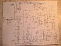
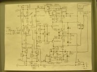
A schematics with indication of locations and values of capacitors which made your amp oscillate, and the exact location of the Zobel network which stopeed it, could help to find the origin of this unattended behaviour.
~~~~~ Forr
§§§
Hi Forr,
It seemed like as small as 18pf caused problems and larger values were worse.
miller feedback (from collector of VAS to base of -diff transistor) miller compensation(from collector of VAS to base of VAS)
or small pf cap across the 47K feedback resistor all caused instability. Without these I get perfect 0V output, well maybe a +/- a millivolt or two.
With a 20 turn pot, I can zero the output quite accuratly. I'm perfectly satisfied with the results, but a little lost as to why. I think the small Cout of the VAS I used may have something to do with it...like 2pf at 25V. Or the larger degeneration of the 1K pot in the LTP.output is like 25-30W into 4Ohms.
PS sorry about the quality, I think it's legible though.
Attachments
In many amps, usually using Zobel compensation/Bucherot cell, something like 10R+100nF in series at output node.
How does this exactly works?
One time, I incidently notice that in the condition of no load (no speaker/no dummy load) attached to the amp, this Zobel makes the amp to oscilate, instead of stabilize it.
What is the mechanism of this Zobel stabilize the amp? Is it OK to make an amp without Zobel?
How does this exactly works?
One time, I incidently notice that in the condition of no load (no speaker/no dummy load) attached to the amp, this Zobel makes the amp to oscilate, instead of stabilize it.
What is the mechanism of this Zobel stabilize the amp? Is it OK to make an amp without Zobel?
Hi Lumanauw,
the Zobel or the full Thiel network do two jobs at the output.
1. the networks give the amp a nearly resistive load at very high frequency where the speaker and it's cable will have a very high impedance due to inductance or if the speaker were to be disconnected.
2. the network attenuates interference picked up by the speaker/cable before you inject this interference through the feedback loop into the inverting input. The Thiel is more effective at this.
All
Q. how do you design the frequency for the resistive part of the network? for both the Zobel and the Thiel. (the most used Zobel is 10r & 100nF >=160kHz)
- Status
- This old topic is closed. If you want to reopen this topic, contact a moderator using the "Report Post" button.
- Home
- Amplifiers
- Solid State
- Loop gain question