I have boards, parts and others....but do not know what is CZ....and other strange codes.
The sistem used is too much intelligent to me....have R1...R2, CZ.... in the place of the resistor value...so i have to find some inform related what is the R1 value.....i am not clever, why not the direct value over the board?...less one step in construction!
Yes, i understand electronics a little...but when people complicate too much i turn confused!
I want an schematic to assemble, as some guys use 680 ohms, others use 1K..... the black Gate capacitor, the adequated value,...the Feedback...i could see that this is not a simple question...hehe
Hey guys!..help!...i want to make it now, as i will travel latter.
regards,
Carlos
Hi Carlos,
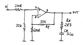
I have attached a schematic which is a bit closer to the PCB than the one in the instructions. As you can see Rz and Cz are the zobel that was added to BrianGT version 2 PCB. I have found on my system the zobel had no effect but others have reported a worthwhile improvement.
What is not shown on my schematic is the connection on the PCB of the signal and power earths. This is important if you were thinking of using "normal" star earth arrangement. My advice is not to it the normal way but follow the instructions and you will have no hum.
The little 4uF blackgates go on the PSU PCB.
A little history may help. (as I remember)
BrianGT and Peter Daniel both sell very similiar NIGC LM3875 PCBs. Both were involved in the design of this PCB. BrianGT has 3 versions that I know of and Peter has sold a couple of versions, originally the same as BrianGT but now I believe Peter does his own version.
The documentation was written by Brian and Sandy and reflect the version 1 of the PCB more closely. A few addition notes were added to cover the addition of the zobel in version 2.
There is a confusion between the web sites and documentation regarding the values of the zobel.
BTW: It looks like I was a little slow in responding. !!!
EDIT: Fixed schematic to reflect correct location of R1
Attachments
Peter Daniel said:Page 3 does not show Zobel yet, here's the current version:
Why in this shematic, you aren't put a capacitor in + signal?
Peter Daniel said:Page 3 does not show Zobel yet, here's the current version:
Page 3 (and my schematic) also shows the 220 ohm series input resistor in a different location.

Peter Daniel said:I know, and so far nobody pointed that out. The schematic drawn by me here, reflects the actual location of R1.
You are right ! Looks like in the Zobel "wars" of '04 we forgot to check the schematic against the actual PCB.
I have updated my schematic in my previous post.
Regards
Re: Oh boys!,... i am terrible sorry!...my mistake...here is Solid State!
Welcome, Carlos.
destroyer X said:Please moderators!...change this to Chip amplifiers forum!
Welcome, Carlos.

Doctor Peter Daniel, very honored with your presence here..also FM
And now friends?...let's snuberizierts oder nichst snuberiziertz...sie problem!
The boards are an astounding, incredible, sensational art work...they are so pretty, that i was thinking if i was assembling or not!....really...it is a crime to solder those boards.
Well...i already done....but feeling a little bit sad...those solders...hummmm...not pretty as the board is...i bent too much the component leads...so...the solder did not made the perfect shape.
This Zobel network, having not oscilation, will do nothing there..so..he can stay there without disturb us.
My dear Greg, you are using 40 x 40 x 300 milimeters "L" shape aluminium, to work as heatsink....it may be working great.
Meus respeitos meu caro FM....my respects my dear FM
I will not listen to the LM3875 for a while, as my "reference" speaker was borrowed by a very close friend...so...i am without any reference.... that speaker is good, as i can perceive fast, before make A to B comparison, what may be the result....i have been using it for long time.
I am sorry Greg...ahahahaha...but those Black Gates will not go to the supply!.... also the pretty supply will be not used with the circuit...will use something more traditional...will let the supplies untouched...too much pretty to receive solder.
I have some Aksa boards here, and i have not courage to use them!
I thank you all, by the attention, in special Mr. Daniel that may have good reasons to be very pride...with Brian also, because the things done for this forum, and the boards quality.
Carlos FM is a strong snuberriziertzen Kamerad, also famous in this forum...very active Mr. FM
Greg Erskine, a dear personal friend...the one i apreciate very much, and the one that made the kindness to offer me, the chance to construct an stereo Gainclone, with the best boards possible to be obtained.
I thank you all,
Sa marche....vitte!...(Fm patented, and borrowed by DX , this registrated trademark..ahahahaha!)
Carlos
Hi Carlos (DestroyerX)
you might want to reconsider not building the power supply boards. One thing that I have learnt from reading these chipamp forums is that there are VERY strong oppinions on how much the power supply affects the sonics of these amps!!!
By all means try with one of your own PS's that you feel comfortable with, but I'd highly recommend also building the PS on the pcb Greg sent you. Otherwise your impression of Chip Amps may not be as favourable as it would have been otherwise In fact I would be very interested to hear your findings on the differences!!
Tony.
you might want to reconsider not building the power supply boards. One thing that I have learnt from reading these chipamp forums is that there are VERY strong oppinions on how much the power supply affects the sonics of these amps!!!
By all means try with one of your own PS's that you feel comfortable with, but I'd highly recommend also building the PS on the pcb Greg sent you. Otherwise your impression of Chip Amps may not be as favourable as it would have been otherwise
In fact I would be very interested to hear your findings on the differences!!Tony.
Hi
& use this schematics with small resistors values 3k and 130(Allen Bradley) like Carlos FM suggests with 4 batteries and 10uF BG-N.With small resistor values sound is faster,more dynamics,more natural.Negative sides & didn't find.What about small resistor values does Peter Daniel and other grands think?
& use this schematics with small resistors values 3k and 130(Allen Bradley) like Carlos FM suggests with 4 batteries and 10uF BG-N.With small resistor values sound is faster,more dynamics,more natural.Negative sides & didn't find.What about small resistor values does Peter Daniel and other grands think?
dariusku said:With small resistor values sound is faster,more dynamics,more natural.
I vote for that.
SSS and Wintermute, Famous Canadien Daniel, Dariushu and amigo FM
The thread, was openned, during one emergency, as i was confused related the pdf file i had, with instructions related the construction of those b-e-a-u-t-i-f-u-l-l red boards made by Brian and his partner, or friend, or follower.... Peter daniel i suppose.
I have any intentions to feed this thread, with pictures, comments or my personal ideas about the subject, as i could see that you already discuss that matter deeply, and some results was obtained.
SSS - A good friend, Mr. Greg Erskine, sent me those chips, as i demonstrate some curiosity, asking him opinnions about, and now, he wants, also, to know what i feel about.... i will tell him near future. This is the reason to visit old friends in this forum
Shalom
Wintermute - I am sure that i never make mistakes!!!!...ahahahahahahahahahahahahahahahah!..laugh because this is the most idiotic thing i already told in my life, as everyone made "zilions" of mistakes!!!
And because i am so special, without defects, the one that never fail(hehe)...i will do exactly the way you suggest...i will construct, assemble, exactly the same way was shown and suggested by factory...by Daniel, by Brian and others gurús.
Dariushu - I will try the Carlos fm method too... and will inform him if needed, as he already know the results.
I will not post any evaluation about the chip.... no opinnion, and no A to B comparison testing.... i will answer directly to Greg Erskine. to avoid to start some figth inside DIY audio Chip Amplifier forum, because of groups of people that share some ideas and others groups that do not believe in those ideas.... and all i want in my life is Coca Cola.... good wife and daugther, and peace brothers!
regards,
Carlos
very diplomatic of you carlos I hope you enjoy listening to your chipamp (and you don't give it the 12 bore!) I wonder whether it will exceed your expectations and if it does whether you will be able to remain silent on the subject
I've finished 1 channel of my first chipamp, only listened to it (mono obviously) for about 30 minutes. It sounded good, though it cannot compete with my trusty old playmaster (100W) at higher volume levels with my relatively inefficient speakers.....the chipamp I assume is clipping on transients and starts to sound harsh.... but in it's configuration (28V rails so only approx 38W into 8 ohms, and very low capacitance PS (1000uF per rail per channel) I guess I can't expect miricals
Tony.
I hope you enjoy listening to your chipamp (and you don't give it the 12 bore!) I wonder whether it will exceed your expectations and if it does whether you will be able to remain silent on the subject I've finished 1 channel of my first chipamp, only listened to it (mono obviously) for about 30 minutes. It sounded good, though it cannot compete with my trusty old playmaster (100W) at higher volume levels with my relatively inefficient speakers.....the chipamp I assume is clipping on transients and starts to sound harsh.... but in it's configuration (28V rails so only approx 38W into 8 ohms, and very low capacitance PS (1000uF per rail per channel) I guess I can't expect miricals
Tony.
- Status
- This old topic is closed. If you want to reopen this topic, contact a moderator using the "Report Post" button.
- Home
- Amplifiers
- Chip Amps
- Schematic for LM3875 wanted fast, as soon as possible