Hello all,
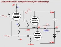
I bought "TCJ Push-Pull calculator" software and simulated this circuit.
It looks very promising. It should be much better than Acoustat
at least it will have much more current for driving electrostatics.
And if bias is increased it will operate in class-A at least first few "Watts"
Now, there is a problem. Software doesn't calculate parts values
resistors, caps ...
And this is where I need your help, tube gurus.
I hope it is not too much work to do this.
Thanks in advance.
P.S.
output tube is 6HV5
gain stage, your choice
Attachments
WTF! 
I'd say right now, you'd better rethink this. One of those tubes fails, and your output goes 2500V hot. That's sufficient to kill should you come in contact with the speaker connection. Furthermore, it's going to be extreamly difficult to reduce the DC offset to an acceptable minimum (and keep it there as the tubes age) with +/- 2500V rails.
Furthermore, check out the heater/cathode voltage rating: it's no more than 200V. The lower VT has that exceeded by better than an order of magnitude.
Nor is it a good design: worse than a Futterman, which isn't as good as a Circlotron.
This is a really bad idea.
Output of course will be coupled with capacitors, so if tube fail or dc voltage offset appears it is not concern. If You have heater transformer good enough to support voltage difference between heater and cathode
without arcing it is OK. Circlotron doesn't provide voltage gain
which is essential for this circuit. In that case as my simulation shows gain is 1.95 so I should have over 1KV drive to get max swing.
With original circuit I need only 6V for 4.5KV swing.
Regards.
without arcing it is OK. Circlotron doesn't provide voltage gain
which is essential for this circuit. In that case as my simulation shows gain is 1.95 so I should have over 1KV drive to get max swing.
With original circuit I need only 6V for 4.5KV swing.
Regards.
Even if capacitor coupled, the charge of the cap at that voltage is enough joules to make you a vegetable in a wheelchair.... if you're lucky 
I agree, this is a bad idea for permanent design, but maybe a good learning experience on the bench (mind furry 4-legged kids with no voltage sense in your home if you have 'em )
I agree, this is a bad idea for permanent design, but maybe a good learning experience on the bench (mind furry 4-legged kids with no voltage sense in your home if you have 'em
)Hello,
Thanks for your concerns guys, but I think it is not really that much
dangerous simply because I have experienced 25KV discharge
from TVs CRT couple of times. And CRT can hold much more charge
than 50nF cap. It is very unpleasant get shocked by this voltage
but far from lethal or even dangerous. Only dangerous part is power supply because it will continue to send current not only pulse like
capacitor. So, stay away from PS and You are fine.
Maybe this fear of high voltage is preventing a lot of diyers to take on something like this.
Regards
Maybe this fear of high voltage is preventing a lot of diyers to take on something like this.
"Fear" ain't got nuttin' to do with it. Big difference between fear and respect, and the prudence the latter demands. I am leery of any VT OTL for that very reason. It's OK for solid state. In that case, blow a final and you burn out your speeks. There isn't usually enough voltage to be deadly. Lose a final in a VT OTL:
Thanks for your concerns guys, but I think it is not really that much
dangerous simply because I have experienced 25KV discharge
from TVs CRT couple of times.
This comparison is not valid. The current requirements for a CRT are quite low, no more than 1.0mA, and so the CRT PS tends to be high impedance. There isn't enough current there to kill under most circumstances. The 2500V rails of this amp will have to source a lethal current, otherwise, it won't work at all.
And CRT can hold much more charge
than 50nF cap. It is very unpleasant get shocked by this voltage
but far from lethal or even dangerous. Only dangerous part is power supply because it will continue to send current not only pulse like
capacitor.
Wrong again! The nominal capacitance for a CRT is 365pF. At 25KV, that's: Q= CV.
(25E3)(365E-12)= 9.125uC
(2500)(50E-9)= 125uC
That's quite a bit more charge on that 50nF capacitor. In terms of energy stored: W= 0.5CV^2:
(0.5)(365E-12)(25E3^2)= 0.114 N * m
(0.5)(50E-9)(2500^2)= 0.156 N * m
You have more charge and more energy in that 50nF coupling capacitor. And you will be storing that much in case there is a failure of one of the finals.
Any way you look at it, this is not a safe design. It would be much better to use a coupling xfmr, so as to isolate that HV from any external connection.
If you insist on doing this, then I'd absolutely forget about trying to turn this into either a kit or production amp. This won't be something "cool" for you to share with anyone who isn't real experienced with HV circuitry.
I believe that you are asking for some serious fireworks at the least, but this has been done before. I really like the design with 4 833A tubes per channel. I thought that I was crazy building an 833A guitar amp.
See this thread :
http://www.diyaudio.com/forums/showthread.php?s=&threadid=56710
See this thread :
http://www.diyaudio.com/forums/showthread.php?s=&threadid=56710
I don't know if you are familiar with Acoustat X commercially available
in mid 80's. This is exactly same amp I already have cloned.
It is up and running but since it is class-A amp doesn't have enough
current capabilities. All I wonted is to build push-pull capable of delivering more current and compare the two.
If You do the search for Acoustat on this forum You will find this link
http://www.twinstaticaudio.nl/twin-dual-mono/index.html and see
that Yes, commercial unit is available and probably approved to be sold. Beside all this I was looking for help finding parts values in
proposed schematic and not to argue safety.
Thanks.
Hi
It wont work.
There is no way to get with those tubes (and the voltages you suggest) enough current to supply the heater transformers stray capacitance at the hf side of the spectrum. A few mA (or even tens) just arent enough. There are also corona effects that have to be taken into account.
wont work, forget it
Hi gorgon53,
I am not sure what are You referring to when You say
"not enough current to supply the heater transformers stray
capacitance at the hf side of the spectrum".
I don't understand what heater trans. has to do with
capacitance or HF.
Anyway, my Acoustat X clone is working just fine with 6HV5
so I will stick to this design.
Regards.
Hi Sasha
The heatertransformers secundary has a substantional straycapacitance to his primary (or screen) and his surroundings, usually a few hundred pf. Indirect heated tubes cannot sustain a high voltage swing between theyr cathodes and the heater. Therefore you would have to couple the transformers secundary to the cathode and supply all the ac-current demanded by the application AND the substantially high currents demanded by the transformers secundary straycapacitance at up to 20kHz at kV levels. This can only be done with BIG transmittingtubes. A few mA just wont do. Besides, even your suggested voltages are high, they are still a bit on the low side, up to 7kVpp would be needed for a Quad (for instance)
The heatertransformers secundary has a substantional straycapacitance to his primary (or screen) and his surroundings, usually a few hundred pf. Indirect heated tubes cannot sustain a high voltage swing between theyr cathodes and the heater. Therefore you would have to couple the transformers secundary to the cathode and supply all the ac-current demanded by the application AND the substantially high currents demanded by the transformers secundary straycapacitance at up to 20kHz at kV levels. This can only be done with BIG transmittingtubes. A few mA just wont do. Besides, even your suggested voltages are high, they are still a bit on the low side, up to 7kVpp would be needed for a Quad (for instance)
I am trying to understand what You saying but
I am still little confused. You are probably referring
to capacitance between cathode and heater and
heater/primary to secondary of the transformer
something like two caps in series from cathode to ground.
Basically output will be loaded with additional capacitance.
Resulting capacitance will be smaller than cathode to heater alone
and this will not load output much more because ESL panel capacitance
is 1-2nF, ten times more than this parasite cap.
Acoustat is working in bridged mode so from 5kV
supply it is possible to get close to 10kVpp.
I don't know why it's working but it does.
Regards.
Attachments
Hi Sasha
Electrostatic speakers arent simple capacitors, gladly, otherwise you would need a reactive current of 1App at 8kVpp and 20kHz.
But straycapitances are!!! 1nF of stray needs 1App at said voltage and frequency.
just do the maths please.
Anyway, for your on safety, if those clearcut and simple things are a puzzle to you please stay away from this project until you have gained all the knowledge and understanding needed to takle such a dangerous project. I can tell you, I once have been hit by 12kV from a HV supply that could deliver 10Adc to the load and I am 1 of the lucky ones getting away alive (burned offcourse)
but Id rather be hit by a train than by high voltage again. If seen picturers of the remains of ppl not that lucky, in one the shoes where recognicable, the rest was black mush....
You see, its all about power delivered into the load (wich means YOU in a worstcase situation) high voltage from a TV set isnt quite the same than HV from a supply that can deliver serious current.
Oh, and I have not been careless when my exident happend, was just "lucky" enough so that several most unlikely and unforeseeable events all happend at the same...so safety is never safe enough...**** happens...for real
Thank You for your concerns about my safety
but it is too late to be scared now since amp is
up and running . Regarding current requirements
for e-stats, there is almost no 20k signal in real music
spectrum hence no need for such current. Remember
we are listening the music not the signal generator.
Even at15k there is so little to be amplified that we
don't need monster amps, otherwise power supply
needed for it will be something like 10kW!
Why is so hard to believe that such amps are real and
work just fine and of course to be sold commercially
needed to be approved by government agency for home use.
Home use means that average Joe is exposed to "lethal danger".
Of course building of it is not for beginners and basic safety rules are
must. By the way I am " trained professional"so I did try it at home.
Hi Sasha,
I looked at the circuit diagram of the acustat, from the drawing I could not say how they solved the heating of the upper tube, maybe they used highfrequency to cut down on the straycapacitance, or a very special designed transformer, no idea, but it is a problem that has to be solved before that thing has a chance to work....otherwise...to much sand in the gears (for my taste) and I would not be supriced if it is down by 10-20db at 20kHz...or...it get some lift by resonces at the hights.
You know, just recently I designed a universal-driver.
My goal was a simulated amplifier capable of delivering
at 20-20kHz and:
at least 800Vpp into 20-200pf and 100kohm,
with a thd better than 3ppm,
and 3th and higher harmoniclevel down by at least 120db,
a phaseshift below 3deg at the passband-ends,'
a outputimpedance of max. 300ohm,
a inputimpedance of min. 100kohm,
no internal slewratelimitations with said load and inputrisetimes of 1nsec,
highest possible outputcurrent (up to Ikmax of the tube) with square or triangle input
I found out:
I NEED A SEPERATE DRIVER, A SEPERATE KATHODEFOLLOWER TO FEED THE STRAYCAPACITANCE OF THE HEATERTRANSFORMER; OTHERWISE NON OF MY SET GOALS CAN BE MET!!!
I needed 8-12 triodesystems (including at least 2 very expensive E288CC) to achieve my goal (well, with the 12 tubes version I exeeded easely my goal in respect to linearity, but I had to cut down a little on the outputvoltage and phaseresponse)
The Supply had to be at least 1000V at 30-35mAdc.
Very high peakoutputcurrents (over 100mA) can be drawn,
but omparable high gridcurrents (up to 1/3 of the outputcurrent) are needed.
The 12-tube mufollower/white cathodefollower-triple tube-cascade I used can have a voltage AND current amplification of over 6000 without external feedback.
The 8-tube approach is a bit faster, distortionlevels can be met, it givs higher outputvoltage but has a gain of around 250 that is just a bit below the set goal for the input sensitivity, neither input nor outputimpedances can be met (there is not enough gain for any fb)
A external feedbackloop is not absolutely necessary, but of advantage to stablice the dc-level at the output, the same fb-loop can be used to adjust the inputsensitivity and impedances but it does not much affect the distortionlevels, especially the 3th and higher.
The higher millercapacitances of tubes other than the E288CC(paired for roughly comparable steepness) worsens distortionproducts in approximate relation to the increase in capacitance.
Now, if I apply my findings to your circuit Sasha, your tube is a good choice, you would not necessarely have to cascade it with a other tube because of the high gain, it also would be tuff to find a even steeper tube without parallelling (a 416 would be cool) but a cascode would have advantages in your circuit, BUT you need current, and when you intend to use a even somewhat conventional heating arrangement (for the upper tube) you will have to use a seperate cathodefollower (or any other suitable amplifier arrangement) for th, otherwise your poor little tube will run outta steam at the high frequencies and not produce full outputlevels at low distortion, you´ll get low output with high distortion instead.
Think of it
But, a amplifier could be build around lets say at least 3 of this tube, or better 5 + a few other tubes,
a amplifier with breathtaking specifacations that would be better than almost any solidstate amplifier, driving directly a electrostat, wow, it would be cool, would make other high-end stuff look like a pair of old shoes...
But, all nowdays safety requirements would be tuff to satisfy in a unit that could be safely sold to customers, seems almost impossible to me at the moment....
I wish I where younger and had enough time to dig deeper into all the probs involved, find solutions and build such a beast, or at least had a usable spicemodel for this tube and a young guy with enough expirience to be trusted in fiddling around with lethal high voltages to build it....
Sasha, looks like whatever I say it would not keep you away from this project ;o)
Tell me, what are you trained in exactly?
I based my opinion on your capabilities on the fact that you said high voltage is not that dangerous because you have expirience with the high voltages of a TV set. Someone that think that the charge (and danger) of a maybe 500pf capacitor is even comparable to what you expirience when getting hit by highvoltage from a source that can send some serious current through you. Now, no trained engeneer, or tecnician with REAL HIGH VOLTAGE KNOWLEDGE, NOT EVEN THE MOST UNTRAINED RADIOAMATEUR WHO BUILDS HIS OWN TRANSMITTERS would think like you do in respect to high voltages.
In regard to a small amplifier driving a electrostat you are propable rigth, the signal MUST be much lower than it should be,
I presumed you want something better, better than transformercoupled systems can do, better than acustat...
Forgiv me, I admit I was wrong...
Case closed
Hi, again.
When I said this 5000V PS is not dangerous I didn't mean
when plugged in but charge from PS capacitors after switched off.
Of course I am not getting even close to the circuit when
operational. Shock from 500nF at 5000V is nasty but not deadly.
Even voltage/current from step-up transformer widely used with e-stats can do some serious damage if touched when played loud.
Looking at PS of the Acoustat I can say it is anything but impressive,
which means no big current is needed for this real world application.
Sometimes when designing circuit we put our goals too high and
end up with conclusion it is hard or impossible to make it.
I am in no way expert in tube or any other circuits but I am good
in cloning and sometimes improving design.
Only big problem with Acoustat was premature tube failure.
When I look at original tubes (6HB5) specs I can't believe
they used this tube http://hereford.ampr.org/Tube4.php?tube=6hb5
I am sure You gonna laugh in disbelief when You see the specs.
How is this possible to work You gonna ask. Well it does, not very reliably but it does and even engineer from Acoustat who these days
offers very expensive upgrades to this amp does not change original tubes??? At least this is mine "non expert opinion" if I have right to one.
And this is why they have so much problems.
My next clone will include better OP amps, feedback caps and resistors.
I don't mind " sand " in this design since some of the best amps
are as we all know very " sandy". I am not very picky I just wonted
something better/cooler than step-up transformer.
Regards.
Hi Sasha
How's the calculations going?
To bad no-one would help you, I would be interested to!
I tried calculating the Totem pole coming from the TJC Push-Pull program, like your attachment earlier, but I'm not sure...
Proposition: Your Acoustat amp was driving your Audiostatic clones to ear splitting levels you said in another post!
Couldn't you then try using 6HB5's with a lot less voltage 1000V for example in totem pole configuration?
- Status
- This old topic is closed. If you want to reopen this topic, contact a moderator using the "Report Post" button.
- Home
- Amplifiers
- Tubes / Valves
- HV Direct Drive tube amp.