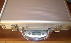
Here is a project about building a fully operational 2 x 200 Watt RMS power amplifier into a small aluminium Poker briefcase.
You can buy the briefcase in any supermarket or hardware store for something like 10$. (It's the small one with 200 chips") )
)
As you can see on the picture below, it looks very nice, and including all parts for the amplifier it weights just around 1500 grams. Not exactly 'heavy hifi'.
You can buy the briefcase in any supermarket or hardware store for something like 10$. (It's the small one with 200 chips
)As you can see on the picture below, it looks very nice, and including all parts for the amplifier it weights just around 1500 grams. Not exactly 'heavy hifi'.
Attachments
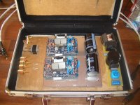
To keep weight and size down, a small but powerful switchmode power supply is used. (Schematic will be posted later).
The use of a switchmode power supply means the power can be easily upgraded. Since power output is mainly limited by the voltage of the power caps. (63V). You can use 80V caps, and put a few extra windings on the transformer to get 350 Watts per channel. (in 8 Ohms). No problem. I just thought 200 W per channel is more than adequate for my 3rd story downtown appartment with neighbors.
I made the switchmode transformer myself, and it is wound with 15 windings on the primary side, and 6 on the secondary side. In between glass wick tape, to get a good safety distance.
But quite easy to build!
It's running 250 kHz, on a ETD14 core. This means it can transfer around 1.2 kW before it is thermally overloaded.
The amplifier modules are ZAPpulse 2.3SE's. That's why i call it Lightforce 1, i plan to upgrade it to Lightforce 2, when new modules are available.
More to come....
Attachments
Hi lars Clausen,
Congratulations to you for your new "LIGHTFORCE" project....
Its a very brilliant idea to run the Class-D with SMPS...lots of high efficiencies from both sides.....combined together!
Keep up the good work...
Every body would be able to learn from it....
Cheers,
K a n w a r
Congratulations to you for your new "LIGHTFORCE" project....
Its a very brilliant idea to run the Class-D with SMPS...lots of high efficiencies from both sides.....combined together!
Keep up the good work...
Every body would be able to learn from it....
Cheers,
K a n w a r
Mmmm. I must be missing something.
Lars, were you talking about the supply in the photo? If so, you said ETD14 instead of RM14
Where are the rest of the components of the supply (mosfets, output diodes...)? Isn't it a flyback design? (Just can't see the voltage divider capacitors or an AC coupling one)
I am also waiting for you to post more details...
Best regards,
Pierre
Pierre: Absolutely right about the RM14. My mistake.
It is a push pull type smps with a coupling capacitor. This way i can avoid the smps' regulation loop to be 'visible' to the audio section. Also a push pull layout is the one that makes the most efficient use of the transformer size.
(Most power per copper and Ferrite).
In the first attempt i was using a rather special driver circuit, that is very simple and safe. But unfortunately the MOSFET's are now so powerful (20A) that they have a bit too high capacitances for the simple driver circuit. That is why i am going to switch to another well proven solution, that i will be posting soon.
Yves Smolders: Actually i would prefer it if you would not use my switchmode for your JP modules.
You will end up getting a sound that is lacking dynamic perfomance, and a messy soundstage. I am sure JP will quickly convince you that the problem is not his modules, but the smps. (hmm for obvious reasons). Well as you know the above problems IMO does not come from the power supply, as any power supply you can think of will give these results.
However using the proposed smps with ZAP modules will give you a highly dynamic, open sound performance with a perfect soundstage. Those are the ones i have been designing the smps for, so i know how it works.
You will end up getting a sound that is lacking dynamic perfomance, and a messy soundstage. I am sure JP will quickly convince you that the problem is not his modules, but the smps. (hmm for obvious reasons).
Well as you know the above problems IMO does not come from the power supply, as any power supply you can think of will give these results.However using the proposed smps with ZAP modules will give you a highly dynamic, open sound performance with a perfect soundstage. Those are the ones i have been designing the smps for, so i know how it works.
Lars Clausen said:However using the proposed smps with ZAP modules will give you a highly dynamic, open sound performance with a perfect soundstage. Those are the ones i have been designing the smps for, so i know how it works.
Thankyou Lars: Looks fantastic and I look forward to using it with my ZP2.3SE modules.
What do you see as the pros and cons of your SMPS over a traditional large transformer PS?

A simple question for Lars...
Why did you choose push-pull topology instead of half-bridge?
If I am not wrong, each mosfet has to withstand twice the rectified bus voltage. That's around 2x320V here, in europe.
It is not easy to find fast and powerful mosfets rated at around 750-1000V, is it?
Why did you choose push-pull topology instead of half-bridge?
If I am not wrong, each mosfet has to withstand twice the rectified bus voltage. That's around 2x320V here, in europe.
It is not easy to find fast and powerful mosfets rated at around 750-1000V, is it?
Ah, ok. Then you have a half-bridge, with a big bus capacitor (400V rated, I suppose) and then a 1uF or similar capacitor, from one of the primaries to bus GND. The other primary terminal to the mosfet bridge. Is that correct?
It was very strange to me that you were making a push-pull! Best of luck with that design. Hope you publish it soon ;-)
Pierre
It was very strange to me that you were making a push-pull! Best of luck with that design. Hope you publish it soon ;-)
Pierre
Ok, Lars.
You have kept it the simple way, haven't you? No output inductor, only two rectifier diodes, no feedback... I assume you run at near full duty cycle all the time. But... isn't that electrolytic 400V capacitor a bit small for around 400W? (with no regulation, as your bus will sag badly under heavy loading, your output will do the same).
Anyway, that will happen as well with a toroid and linear supply!
We are all waiting to see the rest of the circuit.
Best regards,
Pierre
- Status
- This old topic is closed. If you want to reopen this topic, contact a moderator using the "Report Post" button.
- Home
- Amplifiers
- Class D
- Making of Lightforce 1 Class D Powerbriefcase