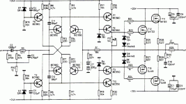
Reference? Hardly.
This is from the time when Menno vanderVeen wrote for Radio Bulletin.
Cheap to construct, the Hitachi's i ripped out of two broken amplifiers at the time.
The drivers do not deliver much current to get a decent slewrate with the 3000pF Css of the mosfets.
At 60KHz(-3dB) and -80dB distortion it is not a great investment to put your money in today.
Attachments
ilimzn said:R7 and R9 are not very useful, and D3 and D4 drop a bit too much voltage, limiting output swing somewhat...
Isn't it beneficial to 'balance' the differential pair of transistors? Because I think the Idea of R7 and R9 is to match R6 and R8. I have matched hundreds of small transistors to get high hf and matched pairs.
If R7 and R9 is not very useful, what is the drawback of puting the resistors on that location? Will these resistors contribute to the noise? By matching the differential transistors I also hope I can get rid of the current resistors R11-R14 (to limit the noise floor).
peranders said:The design is like a blueprint of the Elektor Crescendo 1985 and is "fair" but can be enhanced of course.
You have built many amps from 3886 and 3875. How do you compare this amp to NIGC? Which one do you prefer? I hate to say that I like NIGC better than the standard mini-crescendo (also the elektor crescendo). I don't like the muddy, laid back vocal from the mosfet. I know that the amp depends on pre-amp, but I haven't got the right pre-amp so far.
So, going class-A (with the mosfet) is an approach to have better vocal. And I don't need much power either, so the rear-end is
using 17Vdc!
jacco vermeulen said:Reference? Hardly.
This is from the time when Menno vanderVeen wrote for Radio Bulletin.
Cheap to construct, the Hitachi's i ripped out of two broken amplifiers at the time.
The drivers do not deliver much current to get a decent slewrate with the 3000pF Css of the mosfets.
At 60KHz(-3dB) and -80dB distortion it is not a great investment to put your money in today.
Yes I know. I meant a 'reference' for K135/J50 based amp (mine is more similar to mini-crescendo). My Hitachis are NOS. I just feel responsible to build a good amp out of them

So the slew rate is the problem. Then the front end should have higher rail like that of mini-crescendo? I don't know electronics unfortunately, so I just change the circuit and listen. What do you think with the rear-end having 17V rail? (I don't need high power).
Oh, I also tried to build as carefully as I can so I can get rid of small caps on mosfet legs. This will also increase the slew rate right?
Mosfets have capacitance, as with capacitors current has to run in them before voltage rises.
General rule is : Risetime=0.35/ Cornerfrequency
For a decent output signal at 20KHz, nowadays 150 KHz bandwidth would be the bare minimum (i prefer it to be much higher)
The drivers have to push enough current in the gates of the output mosfets to have the voltage rise fast enough.
A bc560 transistor can handle 500mW, with front end powersupply voltage at 24 volts across collector and emitter the device dies if the current exceeds 21 milliamps.
If the gate of a N channel mosfet still carries -24 volts a single bc560 driver could only deliver 10.5 milliamps before it fries itself to death.
Stacking 2 bc560's has the advantage that they partially share the voltage load.
R19 and R20 are there to protect the drivers from collapsing.
Unfortunately this limits the ability to make the voltage rise fast.
On top of that the bases of T7 and T10 will not be able to receive/release enough current.
Regular bc560's have an Hfe of around 200 at decent output currents.
The current source around T6 delivers only 1 mA to T4 and T5, same with T3, T1 and T2.
Half of the 1mA goes to T1, with a signal on the input T7 is allowed to deliver more current into T1, but no more than T3 will allow to pass through it.
In this design the bandwidth was limited at the entrance to limit TIM distortion, which even then isnt that wonderfull.
Means:
if you wish to make it better you need a driver with higher power rating that will enable to lower the values of R19/R20, higher Hfe of the driver or you have to add a current amplification stage to the circuit.
I've built better 4 stage circuits with BD139/140 drivers for the Mosfets.
Could be worse, the original circuit used carbon resistors, ceramic capacitors and only a 120VA transformer for 80 watts of dissipation.
For those who wonder why 20 watts need 4 TO3 can mosfets: the design was meant to do full class A in 4 Ohm !!
Jacco,
I've found that cascode VAS/driver works quite well for MOSFET output stages if one wants to keep it a 3-stage design. Eg. BC546/556 are then used as the common emitter part in the cascode, and it's C-E voltage kept low enough so the dissipation is small even at a high current, yet you still have the advantage of high current gain. A BD139/140 pair are used as the common base part of the cascode. In this arrangement it is also possible to limit the maximum output current of the driver by inserting an appropriate resistor between the collector of the common emitter and the emitter of the common base transistors in the cascode. This way, whan current is exceeded, the common emitter transistor saturates. Much better recovery characteristics can be had if there is also a small schottky diode across C-B of the common emitter transistor, to prevent deep saturation. Using a cascode in designs like this should not present a problem since the driver stages are powered from higher rails anyway - a loss of a few V due to cascoding is easily compensated for.
Also, if I remember my MOSFETs right, wasn't 1 pair just enough for 20W class A into 4 ohms (with a huge heatsink, of course, or forced air cooling)?
jacco vermeulen said:Reference? Hardly.
This is from the time when Menno vanderVeen wrote for Radio Bulletin.
Cheap to construct, the Hitachi's i ripped out of two broken amplifiers at the time.
The drivers do not deliver much current to get a decent slewrate with the 3000pF Css of the mosfets.
At 60KHz(-3dB) and -80dB distortion it is not a great investment to put your money in today.
Err... Crss for those K135/J50 Hitachi FET's is only 10 resp 40 pF and that's what counts for source followers, not Coss!
BTW Hitachi FET's dont have any such numbers as 3000pF Coss, rather 350 resp 400 pF each.
Say compare to IRF540/9540, these IRF's are much worser regarding capacitances, especially Crss.
The picture you added, I noticed there's those wire wounded source resistors which is a big cause for ocillation, should be replaced with carbon film resistors.
Regarding modifications I would roughly make following changes, add a driving stage between VAS and output FET's, remove C11 and C12 and add a feedback capacitor from VAS to diff stage.
Quiscent current in VAS is around 6 mA, half that value and keep those BC550/560 and change D3 and D4 to a couple of volts higher values(R6, 8 ,19 and 20 must be recalculated) and remove R7 and 9.
And of course make sure output FET source resistors are carbon film.
Cheers Michael
Thank you, Michael, i shouldnt post silly numbers,reverse transfer is indeed that low.
Still, works miracles for teaching me though.
I do take it that separating Vas and driver stage by adding a driver stage between Vas and output stage will be a big improvement to distortion figures ?
How about upgrading the trimpot to a Vbe multiplier, the value of the gate resistors and the feedback ?
The advised heatsink was a 0.4 K/W model, 2 amp bias.
Thanks Jacco for the very informative explanation. I hope I can learn something and have the gut to experiment At least, if the Hitachis get broken, I will not have to buy them again
Spec above audible spectrum, is it really audible?
Have you seen pavel Dudek's DPA330? He did almost everything in the circuit. If circuits like that 20W or the crescendo really need other stages, why are they not there? It's not difficult and not expensive to add 2 more stages correct?
Will the problem discussed here be solved even partially, by adding such stages as found in DPP330? (Without the errorr correction, servo FB and other fancy components)
At least, if the Hitachis get broken, I will not have to buy them again Spec above audible spectrum, is it really audible?
Have you seen pavel Dudek's DPA330? He did almost everything in the circuit. If circuits like that 20W or the crescendo really need other stages, why are they not there? It's not difficult and not expensive to add 2 more stages correct?
Will the problem discussed here be solved even partially, by adding such stages as found in DPP330? (Without the errorr correction, servo FB and other fancy components)
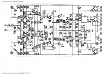
DPA330 schematic
The 2SD760/2SB720 Pavel uses as drivers for the mosfets are great devices:100 MHz, 2 amp max., also by Hitachi.
You can still get them at Nikko elec., not cheap though, expect more than $1.50 the piece.
(i am also still an aficinado of opamp dc-servo's, bipolar dc blocking capacitors are so outdated)
Attachments
The cascoded Vas stage, yes.
But other than that i see more differences than resemblances.
The A75 was the last amplifier i constructed in 1995, after finishing Mr Thagard's 100 watt 1990 mono design, after that 10 years nothing.
The output devices i used for the A75 were 630/9630s because i couldnt lay my hands on TO3's.(see datasheet of the irf230)
Performance of the 20 watter is in no way comparable with the A75.
The A75 pdf's should be good reading, Jay.
They should still be on the download section of PassDIY.
I still need to scan the xerox copies of the Norman Thagard 100 watt design and mail it to a diyaudio member. Anyone else interested in having it can send me a word.
Yes, jacco I'm interested in the Thagard. Please send me also, thank you.
Jacco, I haven't yet checked the pdf but I built A40 once. if I'm not mistaken they differ 'only' on the number of output transistors. And as I can remember they are BIPOLAR! I'm not looking for high class amp here (I have built enough free designs), I'm just looking for a high class amp for my expensive K135/J50 But you seem to like the A75. Hmmm... I think NP himself don't like bipolar?? 
Jacco, I haven't yet checked the pdf but I built A40 once. if I'm not mistaken they differ 'only' on the number of output transistors. And as I can remember they are BIPOLAR! I'm not looking for high class amp here (I have built enough free designs
), I'm just looking for a high class amp for my expensive K135/J50 But you seem to like the A75. Hmmm... I think NP himself don't like bipolar?? - Status
- This old topic is closed. If you want to reopen this topic, contact a moderator using the "Report Post" button.
- Home
- Amplifiers
- Solid State
- Klasse A-versterker van 20 Watt