Hi!
How much voltage can I regulate with TL431? Can I make 300V (or even higher!) with this IC? You know, the TL431+optocoupler style feedback.
It come to my mind, "what if I make a tube amplifier with switched mode powersupply for the plate-supply?"")
You may think, that I'm a "little bit" pervert .....:-D
How much voltage can I regulate with TL431? Can I make 300V (or even higher!) with this IC? You know, the TL431+optocoupler style feedback.
It come to my mind, "what if I make a tube amplifier with switched mode powersupply for the plate-supply?"
You may think, that I'm a "little bit" pervert .....:-D
TL431 is rated at 37V so using it with higher voltages requires additional components in order to ensure that this value is not exceeded.
For example, you may use an auxiliary 12V winding to power the optocoupler and a clamping diode to protect the adjust terminal. A high voltage cascode transistor like MPSA44 would also be a solution.
Note that in order to get the 2.5V reference from 300V, a precision resistor in the lower leg of the voltage divider is required.
Anyway, I think that for such high voltages the discrete approach is preferable.
I would use somethinkg like that:
An externally hosted image should be here but it was not working when we last tested it.
Danko,
I tried the solid state one with IRF HV fets but I found the thing very sensitive to oscilation.
And the quality of the feedback resistors is also very crucial. With some there is ringing, others not.
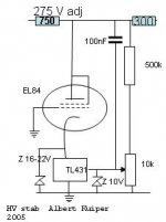
I settled with a tube based diagram. The zeners are there for the overload protection of the 431.
As long as this is running before the PS comes up then the startup is very smooth. I use an indirect heated diode and an input inductance. (Otherwise it will want to sustain the HV due to the feedback capacitor.
It works very fine.
The HV can be set with just so much current that the HV net residue completely disappers.
I don't use a smothing capacitor over the whole unit.
This comes after a output resistor. Something like 10 mF should do.
I tried the solid state one with IRF HV fets but I found the thing very sensitive to oscilation.
And the quality of the feedback resistors is also very crucial. With some there is ringing, others not.
I settled with a tube based diagram. The zeners are there for the overload protection of the 431.
As long as this is running before the PS comes up then the startup is very smooth. I use an indirect heated diode and an input inductance. (Otherwise it will want to sustain the HV due to the feedback capacitor.
It works very fine.
The HV can be set with just so much current that the HV net residue completely disappers.
I don't use a smothing capacitor over the whole unit.
This comes after a output resistor. Something like 10 mF should do.
Attachments
What about this? -> http://sziget.mine.nu/~danko/aramkor/Screenshot-211.png
The TL431 has to regulate onyl 50V. If i'm correct
The TL431 has to regulate onyl 50V. If i'm correct
Eva said:I would use somethinkg like that:
EVA -- the feedback/ref pin on the TL431 is the error opamp "V+in" -- see the Texas Instruments drawing.
You can use the TL431 for a HV supply -- consider it driving an inverting amplifier which drives a current source (i.e. a high voltage MOSFET amplifier). It's a bit more difficult to compensate since you don't have access to the error amplifier "V-in". This was the basis of an article i wrote on a microcontrolled high voltage power supply (with attribution to the folks who first brought it to mind -- Horowitz and Hill).
If you are going to the effort of building a HV regulated supply I would use a better opamp and better reference than the TL431, however.
Attachments
jackinnj said:
EVA -- the feedback/ref pin on the TL431 is the error opamp "V+in" -- see the Texas Instruments drawing.
The op-amp in that TI drawing is driving a NPN output transistor that reverses the polarity of the input signal, so actually the input pins work as if they were reversed. Note that my simplified schematic doesn't include that output transistor, so it still reflects the actual polarity with which TL431 responds.
richwalters said:The tube cad doesn't show the pole compensation required for the TL431 otherwise it can nicely oscillate. In the real world this device can behave otherwise and is one of typical omissions using such computer programs. Bread board and suss it out..
richj
the compensation for the TL431 is discussed in the September 15th 2005 issue of EDN --
the device doesn't have to be looked at as a black box --
SUBCKT TL431 7 6 11
* K A FDBK
.MODEL DCLAMP D (IS=13.5N RS=25M N=1.59
+ CJO=45P VJ=.75 M=.302 TT=50.4N BV=34V IBV=1MA)
*V1 1 6 2.495 ; used for fixed reference, replaced with EB1 Limiter
EB1 1 6 Value = { IF ( V(7,6)> 2.495, 2.495, V(7,6) ) }
R1 6 2 15.6
C1 2 6 .5U
R2 2 3 100
C2 3 4 .08U
R3 4 6 10
G2 6 8 3 6 1.73
D1 5 8 DCLAMP
D2 7 8 DCLAMP
V4 5 6 2
G1 6 2 1 11 0.11
.ENDS
note that the model on TI's website lacks the reactive components.
- Status
- This old topic is closed. If you want to reopen this topic, contact a moderator using the "Report Post" button.
- Home
- Amplifiers
- Power Supplies
- TL431: Can it regulate 300V DC?