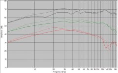
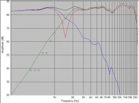
This is my first self-designed loudspeaker project. It uses Seas 27tdfc tweeter with a waveguide bought from finnish loudspeaker supplier. Tweeter's fr with and without waveguide on axis, 30 and 60 degrees off axis is attached as an image.
The woofer is the successor of the well known 850488, 830870.
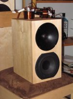
The enclosure is 7,7 l ported made of 18mm birch board. The external dimensions are 31*23,6*17,6 cm. The port is 50x150 mm and fb is somewhere near 60 hz.
I am very pleased with the results, the sound is balanced and neutral.
The woofer is the successor of the well known 850488, 830870.
The enclosure is 7,7 l ported made of 18mm birch board. The external dimensions are 31*23,6*17,6 cm. The port is 50x150 mm and fb is somewhere near 60 hz.
I am very pleased with the results, the sound is balanced and neutral.
Attachments
The waveguide is from hifitalo (www.hifitalo.fi). They use it in their kit aw-10hqi with an aluminum tweeter. It is made of plastic and it's about 22mm deep. The throat opening fits the 27tdfc perfectly.
John Krutke has also made some measurements with the same tweeter but a different waveguide.
John Krutke has also made some measurements with the same tweeter but a different waveguide.
Hi Pajazo,
I'm going to have to wait to get home to see if I can download the finnish translator on my PC at home. My Finnish is not so strong (pun intended)") . In the meanwhile, if you could e-mail them and let them know that there are raving lunatics desperate for such devices (me in particular) here in the USA, that would be greatly appreciated. I'd hate to have to buy an airline ticket to Finland just to get this thing
. In the meanwhile, if you could e-mail them and let them know that there are raving lunatics desperate for such devices (me in particular) here in the USA, that would be greatly appreciated. I'd hate to have to buy an airline ticket to Finland just to get this thing  .
.
cheers,
AJ
I'm going to have to wait to get home to see if I can download the finnish translator on my PC at home. My Finnish is not so strong (pun intended)
. In the meanwhile, if you could e-mail them and let them know that there are raving lunatics desperate for such devices (me in particular) here in the USA, that would be greatly appreciated. I'd hate to have to buy an airline ticket to Finland just to get this thing .cheers,
AJ
I learn more about waveguides every day. From what I understand today, An "optimal" waveguide shape is specific to the crossover frequency for the driver it is mounted in front of AND the dispersion of the lower frequency driver it is paired with. An off-the-shelf waveguide may provide better response from a driver, though not as good if it were tailored to the system it is included in.
A waveguide also induces backpressure forces on the driver diaphragm. This may induce distortion. For this reason metal domes seem to be favored.
This is timely. I'm encouraged by the interest expressed here. I've copied some posts by Pooge and others from the AA forum that provide the formulas needed to plot "optimal" shapes. I plan to slash my way through Excel this week to see what I can come up with.
The following are excerpts from some of those posts and are shared to whet your appetite. For the “full” story, go to Audio Asylum and search “waveguide’
Waveguide shape
Pooge ( A ) on March 29, 2005 From "Sound Radiation in Acoustic Apertures" by Geddes, JAES, April 1993:
"A short waveguide may not yield the best directivity control at the low frequencies, while a long waveguide will yeild poor high-frequency results (on axis) due to the aperture diffraction since the first "hole" [in the axial frequency response] is found to be located at ..."
It was found that "diffraction limit" for a circular mouth is
kR = 15.0/sin^2(angle);
where R = the length of the horn
K is the wavenumber, or (2*pi*f)/c,
where c=the speed of sound
"This frequency will be called the aperture diffraction limit for a waveguide. Above this value the frequency response and the directivity will be strongly affected by the mouth diffraction. Below this limit the waveguide will behave as a directive point source. [The formula] can be used as a rule of thumb for deciding the correct length of a waveguide." Thus:
"kR" should be less than "15.0/sin^2(angle)".
What is clear,… is that a baffle and a radiused termination of the waveguide into the baffle will reduce the diffraction effect that causes the condition for which the hole in the freqency response was found. The final curve at the mouth is not part of the 'horn flare', which is what the waveguide equations determine. It's simply a radius to reduce diffraction (and probably reflections back down the horn) from the mouth. There probably is some theoretical basis for this, but I would guess that empirical is pretty good. I think Pooge is right that Geddes uses a ~2" radius - simply blend that into the curve for the flare as smoothly as possible and you should be in good shape.
For anyone that wants to play with other throat sizes and waveguide angles, here are the formulas:
[(y^2)/{((a/2)^2)*sin^2(ang)}] - [(x^2)/{((a/2)^2)*cos^2(ang)}] = 1
where a= 2r/sin(ang)
where r= the radius of the throat or y at x=0
and ang=the angle from the x-axis to one wall of the waveguide.
Hi Pajazo,
God work, can you tell us how it handles sound pressure? HiFi Talo does not speak too good english.
You can take a look at www.dxt.dk and/or http://www.seas.no/index.php?option=com_content&task=view&id=184&Itemid=179
"coming soon to a shop near you"
Jon
SEAS
God work, can you tell us how it handles sound pressure? HiFi Talo does not speak too good english.
You can take a look at www.dxt.dk and/or http://www.seas.no/index.php?option=com_content&task=view&id=184&Itemid=179
"coming soon to a shop near you"
Jon
SEAS
1) Great looking speaker, great choice of drivers, with resultant great sound I'm sure.
2) How did you finish the cabinets pajazo? Very nice woodwork!
3) Per Ed: "An 'optimal' waveguide shape is specific to the crossover frequency for the driver it is mounted in front of AND the dispersion of the lower frequency driver it is paired with. An off-the-shelf waveguide may provide better response from a driver, though not as good if it were tailored to the system it is included in."
In this case it would be nice to be able to fabricate one's own waveguide, specific to the application - I'm thinking with a block of wood cut on a lathe perhaps, although it would ideally be a programmable lathe. Would look nice too - would integrate well with the baffle.
sdclc126
Interesting to revisit this thread ~ 2 years later. A spreadsheet in excel is available for viewing/printing any variety of waveguide profile. JoshK may be doing some additional work to set the entry angle @ the throat. Send me your address if you are interested.
See Ya!
Interesting to revisit this thread ~ 2 years later. A spreadsheet in excel is available for viewing/printing any variety of waveguide profile. JoshK may be doing some additional work to set the entry angle @ the throat. Send me your address if you are interested.
See Ya!
- Status
- This old topic is closed. If you want to reopen this topic, contact a moderator using the "Report Post" button.
- Home
- Loudspeakers
- Multi-Way
- Seas 27tdfc + waveguide and Peerless 830870 project