hi ya,
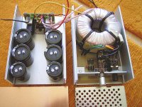
i have my ultra-compact high-cap snubberized t-network inverted gainclone (phew !) in progress. the whole thing measures 105 x 105 x 165 mm (~4,1 x 4,1 x 6,5 "). one decision is left to make:
the halfs of the alumimum box shown are to be put together open side to open side and fixed with screws on front and back panel.
what would you prefer: trafo just above the chip and shielding both trafo and chip with and / or copper sheet and the magnetic stuff on the right (salvaged from a dead computer monitor)? wiring from rectifiers to psu would be 60 mm (~2,4").
or should i turn the right half so that the trafo is above the capacitors and the cabling from rectifiers to psu is 220 mm (~8,7") ?
i´m not shure if there is any drawback in the quite long cabling, but otherwise i think the inductivity shouldn´t affect as it would be before the caps. i dislike the idea of having the trafo directly above the chip ...
i have my ultra-compact high-cap snubberized t-network inverted gainclone
(phew !) in progress. the whole thing measures 105 x 105 x 165 mm (~4,1 x 4,1 x 6,5 "). one decision is left to make:the halfs of the alumimum box shown are to be put together open side to open side and fixed with screws on front and back panel.
what would you prefer: trafo just above the chip and shielding both trafo and chip with and / or copper sheet and the magnetic stuff on the right (salvaged from a dead computer monitor)? wiring from rectifiers to psu would be 60 mm (~2,4").
or should i turn the right half so that the trafo is above the capacitors and the cabling from rectifiers to psu is 220 mm (~8,7") ?
i´m not shure if there is any drawback in the quite long cabling, but otherwise i think the inductivity shouldn´t affect as it would be before the caps. i dislike the idea of having the trafo directly above the chip ...
Attachments
I built a similar amp into the same chassis and had the same issue, i solved it by putting a 6mm thick peice of copper plate inside the housng to divide it into two boxes. This worked pefectly and even though my lm3886 is only maybe 4-6cm above the tranny i have no humm what so ever.
fil
fil
- Status
- This old topic is closed. If you want to reopen this topic, contact a moderator using the "Report Post" button.