I was wondering if anyone here knows How to calculate what resistor you need when paralleling amplifiers? it seems like one of those things that could go drastically wrong if the wrong choice is made.
I had an idea to make a low watt amp of a bunch of TPA6120s
they are current amplifiers so would that make any difference when paralleling them? (or make it impossible)
I had an idea to make a low watt amp of a bunch of TPA6120s
they are current amplifiers so would that make any difference when paralleling them? (or make it impossible)
Minimal load impedance by TPA 6120 is 8 Ohm. So if you use two pieces of this circuit ( four amps ), which will have connected outputs together through this resistor ( each ), you can get output power into 8 Ohm load cca 6 W. Distortion will be in this case very good ( bellow .001 % ), but DF will be low, only four ( 8/2 ), so sound will be similar to single ended tube amp.  If you like similar sound, go on.
Upupa Epops said:Minimal load impedance by TPA 6120 is 8 Ohm. So if you use two pieces of this circuit ( four amps ), which will have connected outputs together through this resistor ( each ), you can get output power into 8 Ohm load cca 6 W. Distortion will be in this case very good ( bellow .001 % ), but DF will be low, only four ( 8/2 ), so sound will be similar to single ended tube amp.If you like similar sound, go on.

The load-sharing resistor is not limited by the minimum impedance of the amp. So you could use much lower load sharing resistors than 8 ohms, like the typical 0.1 to 0.5 ohms. Just make sure that the gain of all of the paralleled amps is very closely matched so that current does not flow between the amps via these resistors.
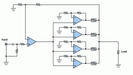
And if you want to keep the Damping Factor high (low output impedance), then you can put the paralleled amplifiers inside the feedback loop of an opamp. This will effectively remove the load sharing resistors from the load - the opamp will adjust the output voltage to remove the effect of the voltage drop across these resistors.
This circuit is very fast, so serial resistor protect output against capacitive load and at datasheet is 8 Ohm recomended as minimal value. Sure, if you all connect into loop, you get lower DF, but circuit will be relatively complicated and PCB will must be designed closely. 
Thanks for all the replies!
I was actually thinking of using more chips per channel (4 or 5) but 2 is a good place to start.
So if i put the load sharing resistors inside the feedback loop, then all of the chips would be getting their feedback from the same node (the final output) ? If they are sharing that node, could they also share the actual feedback resistor, so it is exactly the same value for all the amps?
Ok, I don't quite follow your line of thinking, but basically what I suggested above entails enclosing the parallel amp inside the feedback loop of an opamp. (see attachment). Each individual amp in the parallel amp still has its own output (load-sharing) resistor, and these absolutely must be outside of each chip's feedback loop.So if i put the load sharing resistors inside the feedback loop, then all of the chips would be getting their feedback from the same node (the final output) ? If they are sharing that node, could they also share the actual feedback resistor, so it is exactly the same value for all the amps?
In the attached schematic I have drawn a simplified four-way parallel amp inside the feedback loop of an opamp so that you can get the idea.
Discalimers: This is intended to be representative only and is not a tested design. There are no component values; you will have to choose them appropriately. Most of the National chips are stable at gains of 10 or higher, so set the gains appropriately, and match them very closely. Also note that the overal gain for the input opamp loop must be greater than the gain for the chipamps, even if the opamp is unity-gain stable. As drawn, the circuit probably has some nasty DC offset problems (especially with all the + inputs of the chipamps all tied directly together), and I would personally take extra steps to reduce DC offset.
Attachments
macboy said:
Ok, I don't quite follow your line of thinking, but basically what I suggested above entails enclosing the parallel amp inside the feedback loop of an opamp. (see attachment). Each individual amp in the parallel amp still has its own output (load-sharing) resistor, and these absolutely must be outside of each chip's feedback loop.
In the attached schematic I have drawn a simplified four-way parallel amp inside the feedback loop of an opamp so that you can get the idea.
[/i]
I agreed with macboy. In addition, I would add Cap in the feedback to ensure unity gain of each chip. Also, individual zobel of each chip will be helpful.
Good luck,
methar said:In addition, I would add Cap in the feedback to ensure unity gain of each chip.
You can't use a cap on the feedback loop of a current-feedback op-amp.

the outer loop op amp has to be slower than the paralleled output op amps - not hard when you're using 100 MHz cf amps inside
a gain of +2 in the output amps makes for easy R matching and doesn't amplify offset too much
load C isolation may still need attention, but a high frequency lossy ferrite or the usual load isolating resistor+inductor (outside the feedback loop!) should work
a gain of +2 in the output amps makes for easy R matching and doesn't amplify offset too much
load C isolation may still need attention, but a high frequency lossy ferrite or the usual load isolating resistor+inductor (outside the feedback loop!) should work
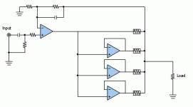
Yes. But you can get away with small ones, like 0.1 or even 0.05 ohms.What about something like this: similar to macboy's schematic. Using paralleled amps at unity gain inside the feedback loop of an opamp. Would the paralleled amps still need output resistors?
Be very aware that this can only be done if the amps that are used are unity-gain stable. (I only mention this because the National LMxxxx chip amps are not, and I just know that someone will wonder if it can be done with them. Answer: No.).
If you are going to use unity-gain stable amps, then you can hook it all up like the following, and eliminate the extra opamp on the input. Note all four opamps in the schematic are identical power opamps. (also note that this schematic generally assumes voltage-feedback opamps. With current-feedback opamps, you can't use the cap across the feedback resistor, and you can't configure it for unity gain by tying the output to '-' input).
Attachments
fwiw -- for the first set of paralleled LM4780 amps I built I matched the resistors to 0.1% -- and it worked quite well. on the second set with production PCB's I matched to 0.01% (inside of 1/10th of an ohm) -- the distortion was about 0.001% lower -- which probably doesn't mean a whole lot -- since the world of probablility, noise and statistics...is the world of noise, probability and statistics. The direction was better, that's all I can conclude, and a bag of 100 Yaego metal film resistors isn't that expensive.
I used an HP3478A DVM for the matching -- these are now cheaper than a new Fluke 177 handheld (although you are tied to the A.C. line).
I used an HP3478A DVM for the matching -- these are now cheaper than a new Fluke 177 handheld (although you are tied to the A.C. line).
Great ideas, I too would like to build a 4 to 8 piece tpa amp..
I want to avoid using any resistors in series with the load.
Would I just use a ferrite cylinder as a core for several loops of output wire?
Are these the snap-together type seen on power power lines?
Can some one post some examples?
What would be some starting point values for components in these two options for isolating the load C from the amp outputs?
My prototype TPA will oscillate if I do'nt keep the headphone cable short and still.(I use 24 ohm phones and no resistors, btw)


Lewis
jcx:...load C isolation may still need attention, but a high frequency lossy ferrite or the usual load isolating resistor+inductor (outside the feedback loop!) should work .
I want to avoid using any resistors in series with the load.
Would I just use a ferrite cylinder as a core for several loops of output wire?
Are these the snap-together type seen on power power lines?
Can some one post some examples?
What would be some starting point values for components in these two options for isolating the load C from the amp outputs?
My prototype TPA will oscillate if I do'nt keep the headphone cable short and still.(I use 24 ohm phones and no resistors, btw)


Lewis
Re: Great ideas, I too would like to build a 4 to 8 piece tpa amp..
good luck. the purpose of the resistors isn't parasitic elimination -- that's for the RC network consisting of the 2.7R/100n combo -- let us know how long your chipamp lasts.
ljordan said:
I want to avoid using any resistors in series with the load.
good luck. the purpose of the resistors isn't parasitic elimination -- that's for the RC network consisting of the 2.7R/100n combo -- let us know how long your chipamp lasts.
- Status
- This old topic is closed. If you want to reopen this topic, contact a moderator using the "Report Post" button.
- Home
- Amplifiers
- Chip Amps
- paralleling amplifiers.

![parallel-amp[1].gif](/community/data/attachments/34/34994-d8411b9f8eedac65bc8a080ea48360fc.jpg)

