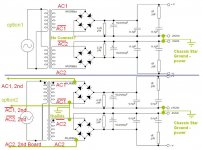
Sooo.... I'm trying to put together the Brian GT power supply for the snubber PS. I've got one transformer and 16 diodes to deal with. I'm about to connect it as shown-- using option #2 in the attached picture (taken from chipamp.com and annotated with what I suppose are the correct connection names). This means that I'm going to tie the center tap together and ground it, as well as ground the "ground" outputs, all to the star power ground. Is this correct?
(I've also changed the primary to reflect what I believe I have going on in #2)
I note that option #1 is what he shows on the web site, note that the transformer is shown floating, nothing on it is grounded. Seems odd to me. Anyway, just trying to do this without blowing something up like I normally do.
Comments on how to connect the xformer to the board with one xformer insteand of 2, and using all appropriate grounds?
Attachments
If you are doing a simple stereo amp, then just connect as Brian describes. If you are then getting problems with ground loops and hum, then start making changes. Not sure what you are saying about having one transformer and 16 diodes. You will only need 16 diodes if you have two transformers and two power supplies. With one transformer you connect to one power supply board, the board has provision to power two amps (2*V+, 2*PG+, 2*PG_, 2*V-).
Good luck with the project,
Chris
Good luck with the project,
Chris
If you have 16 diodes, that means you have enough for two diode bridges (ie. two power supply boards). If you are only using one transfo, then you will have to split the leads of your transfo and connect to the two bridges.
in other words, connect two wires to each secondary lead from your transfo, and then take one set connect it to one bridge same way you would having a single tranfo/single bridge setup. and then do the same with the other set of leads and the other bridge.
in yet other words, connect your bridges in parallel to your transfo.
this is the approach i am taking also, although my transfo is not center tap.
lgreen said:Sooo.... I'm trying to put together the Brian GT power supply for the snubber PS. I've got one transformer and 16 diodes to deal with. I'm about to connect it as shown-- using option #2 in the attached picture (taken from chipamp.com and annotated with what I suppose are the correct connection names). This means that I'm going to tie the center tap together and ground it, as well as ground the "ground" outputs, all to the star power ground. Is this correct?
(I've also changed the primary to reflect what I believe I have going on in #2)
I note that option #1 is what he shows on the web site, note that the transformer is shown floating, nothing on it is grounded. Seems odd to me. Anyway, just trying to do this without blowing something up like I normally do.
Comments on how to connect the xformer to the board with one xformer insteand of 2, and using all appropriate grounds?
I labelled the AC secondary windings in the schematic:
http://www.chipamp.com/images/ps-rev3-sch.gif
(if picture is still the old picture, reload/clear your cache)
For wiring 2 boards to 1 transformer, the same wires are connected in both board (parallel configuration).
With regards to the ground, the grounding is done from the amp pcb, with the CHG (chassis ground) pads on the amp boards connecting to both the chassis and the AC gnd connection coming in from the IEC connector.
Let me know if you still have questions. If I don't reply to this thread, drop me an e-mail, as I might miss this reply since I don't have e-mail notification turned on.
--
Brian
Brian,
I hate to show my ignorance but... are you saying that the center tap doesn't get connected to anything if you using the snubber? I'm in the process of building one of your LM4780's. Almost have the chassis done & will start on the boards this weekend. By the way I hope the 4780 sounds as good or hopefully even a little better than the GC I built with your very 1st boards.
Thx
kestrel200 said:Brian,
I hate to show my ignorance but... are you saying that the center tap doesn't get connected to anything if you using the snubber? I'm in the process of building one of your LM4780's. Almost have the chassis done & will start on the boards this weekend. By the way I hope the 4780 sounds as good or hopefully even a little better than the GC I built with your very 1st boards.
Thx
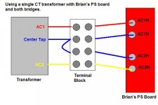
The transformer shown is not a center-tapped transformer, so there are no unwired connections. The transformer shown has dual secondary windings, which are each fed to the bridge rectifier seperately. The grounds are later referenced to each other on the amp board. (PGND+ and PGND-)
As for a center-tap transformer, you can follow the method shown in the LM3875 manual on the website, which should work for this board.
Often a center-tap transformer can be converted to dual secondaries, as the center-tap is often just 2 secondary windings with the middle wires tied to a common lead.
Let me know if there is still confusion.
--
Brian
Hi Brian,BrianGT said:
As for a center-tap transformer, you can follow the method shown in the LM3875 manual on the website, which should work for this board.
I understand this but have questions. Center tapped transformer with 3875 schematic showing use of 4 doides and jumpers on pcb.
1) Would there be an advantage to splitting center tap lead without splitting to dual coils and soldering to AC1H and AC2N using 8 diodes?
2) Why is it better to have dual rectifier bridges?
Phil
I do not think that is possible. Take a look at that centertap and see if it possible to separate the centertap connection in two! Often enough it isThis should help.?!.?
") You are gonna have trouble, if the grounding of AC1 and AC2 meets at some point later
You are gonna have trouble, if the grounding of AC1 and AC2 meets at some point later You would be better of using Brians suggestions in the manual, for a centertap!
 Steen.
I think you would see smoke coming out! The two taps on the trafo are in opposite phase! You cannot make two independent AC sources from that CT trafo. Save the 4 diodes for another project and do as BrianGT suggests in the manualWhat would happen if I wire it as Chris's pic shows?
None! You just have to wire up a CT trafo in another wayWhat advantage would dual rectifier bridge be?
A CT is just as good as a dual secondary, but not so flexible in the way of implementation! Hope this helps. Steen.
- Status
- This old topic is closed. If you want to reopen this topic, contact a moderator using the "Report Post" button.
- Home
- Amplifiers
- Chip Amps
- Brain GT 3886 PS question