So, for today we have a special treat:
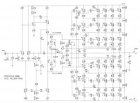
www.passlabs.com/temp/800a_schem.tif
The 800A was designed in 1975 and was my first
commercial product. A total of 150 or so were built,
the majority going to Asia.
The Bag O Fun posting shows the original brochure with
the relevent specs, story, and pictures.
These were hand built by Rene Besne and I, initially in
my garage and living room. I made the PC boards myself.
The design is notable for several things:
Like H.G.Wells' martians, the output stage is a study in
threes: A triple-series, triple parallel, triple darlington
follower. I think it was the first and last of its kind.
The output stage was idled at about 200 watts, or about
1/2 of what you would expect from a Class A circuit.
The output devices were Motorola 2N5878/76, chosen
for their higher bandwidth (at the time) over 6031's
and 5631's (1 MHz). Interesting to note that the
Levinson ML-2's later used the 5800 type chips also.
I believe this was probably the first solid state amp to
eschew the use of an output inductor.
The bias circuit was the infamous "dynamic bias" which
adjusted the bias voltage in real time to keep both halves
of the output stage in conduction to 200+ watts. You can
see it in Q5, Q6, Q10, and Q11. Its function was helped
along by D22 and D23 and R73 and R74 which provided
a breakpoint in the transfer curve, smoothing the cutoff
curve.
You can see variations of this type of circuit in later work
by Hawksford, Cordell, and of course companies like JVC
and Pioneer and a host of lesser known brands.
You will see VI limiters in Q7 and Q12, but they have been
set at fairly high current values and have integrators to keep
them from tripping into electrostatic speakers.
The front end is prosaic enough, and was designed to be
driven by a buffer which was on a separate assembly in
the amplifier.
Several of the resistor values are pulled from memory here,
as the only schematic copy I have is of very poor quality.
Threshold built these amps for about 3 years, along with
the 400a and the 4000, but then abandoned the approach
because by then there were too many imitators offering
circuits which called themselves Class A but which idled at
almost no current, tarnishing the image of the product.
The notion of idling output stages at low bias and ramping
it up on demand has lived on; check the literature on Krell's
Sustained Plateau Bias.
What is the difference between 800 A and T 800 D ?
The difference of which I can be certain is that I had nothing to
do with the T800, and I have no information on it, other than
that it was produced long after I sold my interest in
Threshold and exited.
As far as my best amp, they all are, each in its own way.")
The difference of which I can be certain is that I had nothing to
do with the T800, and I have no information on it, other than
that it was produced long after I sold my interest in
Threshold and exited.
As far as my best amp, they all are, each in its own way.
And I always thought Krell has been the inventor of this kind of circuits......The notion of idling output stages at low bias and ramping it up on demand has lived on; check the literature on Krell's Sustained Plateau Bias
Mr. Pass:
I can imagine that pure Class A is still superior than automatic bias level adjustment (though it works in "real time") but I wonder if this method of biasing basically could have any real advantage sonically over a fairly high biased ordinary Class A/B amp (of course proper application is presupposed)?
If that were the case why it isn`t found more often in commercial (or DIY as well) designs?
Mr.Pass,
Can this schematic be used with upgraded semiconductors to provide high quality music in PA and Disc rigs? Will it better the sound of the Leach SuperAmp?
I have MJ21193/21194 devices in mind for the outputs, while I have not investigated into the other stages' devices.
Any comments.
Can this schematic be used with upgraded semiconductors to provide high quality music in PA and Disc rigs? Will it better the sound of the Leach SuperAmp?
I have MJ21193/21194 devices in mind for the outputs, while I have not investigated into the other stages' devices.
Any comments.
are this output stage a kind of multi cascode (to avoid memory distortion) or is it a serial circuit to enhance the max Vceo?
regarded the Vceo enhance I have heard about an application note from Motorola arround 1973 - 1975. Unfortunately I haven't exactly title of this application note. Perhaps one of you know this.
Here the presently weblink for the schematic of Threshold 800A ("800 A")
Threshold-800A.jpg (image)
regarded the Vceo enhance I have heard about an application note from Motorola arround 1973 - 1975. Unfortunately I haven't exactly title of this application note. Perhaps one of you know this.
Here the presently weblink for the schematic of Threshold 800A ("800 A")
Threshold-800A.jpg (image)
are this output stage a kind of multi cascode (to avoid memory distortion) or is it a serial circuit to enhance the max Vceo?[/url]
We were using some of the faster output devices of the time,
like 2n5878/76, but the second breakdown on them was not
so good, plus of course there was a lot of dissipation going on.
The triple series kept the voltages nice and low.
That it did not seem to have been done previously was just
the cherry on top.
Dear Mr. Pass, thanks for your reply.
Regarded the exactly title of the concerning motorola application note I have found an advice from the old German magazine "Funkschau" (1977 issue 4, page 61/161): By the topic "Hifi Nachrichten" ("Hifi News") is mentioned, that Motorola has developed in their European consumer labor a new concept to share the power dissipation (and the Uceo of course) and a new series of bipolar TO-3 power devices especially for the european marked (BD364/365 for 50V, BD366/367 for 60V and BD368/369 for 80V Uceo)
There is additionally mentioned, that the max. value of serial devices could be four pieces (i. e. Uceo 320V) The figured schematic is basicly the same as the push pull power buffer in the 800A
But unfortunately there are no advices of the orig. article of this application note from Motorola. Even by "datasheetarchive" I don't found this article only a list with short form data of all BjT's from this aera, see about
BD368 datasheet and Application Note, Data Sheet, Circuit, PDF, Pinout | Datasheet Archive
and open PDF file
If I have the exact title of this application note, I'm happy because I can then order a copy of this via telerent bookstore (interlibrary loan).
Thank you very much for your advices.
Last edited:
There's not really a lot to say about this. Running outputs in multiple
series/parallel is pretty straightforward, although you have to compensate
the frequency stability of some systems as you apply more series stages.
The only reason to do this is to avoid high voltage breakdown of the
devices. In the 800A it was very important to stay out of the second-
breakdown region of the bipolar transistors due to the high currents
involved. The result was very reliable - after the initial shakedown, I don't
recall seeing any failures.
similar approach is to find by the Vox "Supreme" instrumental amplifier - go to the schematic by post #79 about
http://www.diyaudio.com/forums/soli...odels-quasi-complementary-power-output-8.html
The theory of operation I don't understand exactly, especially the reason, why for the Tr16 and Tr17 also was used a 2N3055 instead a medium signal type like MJE243.
http://www.diyaudio.com/forums/soli...odels-quasi-complementary-power-output-8.html
The theory of operation I don't understand exactly, especially the reason, why for the Tr16 and Tr17 also was used a 2N3055 instead a medium signal type like MJE243.
- Status
- This old topic is closed. If you want to reopen this topic, contact a moderator using the "Report Post" button.
- Home
- Amplifiers
- Pass Labs
- 800A Schematic