I've just finished my 2nd subwoofer project and since then I've decided to route all my <80Hz signals to the sub using my receiver. To up the bar on the surround speakers (now an assorted bunch of Mission loudspeakers) I've decided to build new ones.
I'm thinking of using Seas' T17 or T18 coaxial loudspeakers for all 6-channels as that would solve my time alignment problems as well, as I don't have to go for a mtm configuration for the center and all loudspeakers would truely be identical.
Unfortunately I've only found a handful of designs based on these loudspeakers of which Tony Gee's USB is close to what I'm looking for. But his design is the only 'audiophile' design I've seen, which is what I'm looking for, not some ill-researched sunday evening jobby. So what's with the lack of designs for these loudspeakers?
Am I missing something here, and are these coaxial loudspeakers not very well suited for the audio enthusiast? Or is there something else I missed?
Best regards,
Sander Sassen
http://www.hardwareanalysis.com
Go to madisounds (www.madisound.com) online discussion board and do a search there. There have been several discussions about these drivers there. Madisound also have a few designs for these on their website somewhere ")
/U.
/U.
Thanks Nisbeth but that forum is a nightmare to navigate, let alone find anything. The only design Madison lists 'supposedly' is from a Seas engineer, which lacks vital information.
Best regards,
Sander Sassen
http://www.hardwareanalysis.com
Best regards,
Sander Sassen
http://www.hardwareanalysis.com
Hi Sander, there is an official SEAS design for the T18 driver. Details can be found at the Madisound website.
This looks to be a good design, and is at least a good starting point.
the link is
www.madisound.com/Seas H1144 Box and Xover.pdf
Let me know if there is still information missing that you need. I have extensive experience of working with concentric drivers, so can give you some pointers.
Andrew
This looks to be a good design, and is at least a good starting point.
the link is
www.madisound.com/Seas H1144 Box and Xover.pdf
Let me know if there is still information missing that you need. I have extensive experience of working with concentric drivers, so can give you some pointers.
Andrew
Andrew,
I stumbled across that one also, as per my reply to Nisbeth, unfortunately that pdf is pretty vague, and doesn't list anything specific but a box volume and a proposed filter. What I'd like to know is the following:
- What are the benefits of using the T18 over the other coax drivers?
- What would be a preferable xover frequency for the T18?
- In a small 6-liter enclosure will I need to use baffle step correction in the filter?
Best regards,
Sander Sassen
http://www.hardwareanalysis.com
Lusso5,
Thanks for sharing that bit of info, but as mentioned I'm looking for some small, bookshelf type of design, can't really fit six ML TQWTs in my living room, and don't need to either, I have all the bass I need.
Best regards,
Sander Sassen
http://www.hardwareanalysis.com
Thanks for sharing that bit of info, but as mentioned I'm looking for some small, bookshelf type of design, can't really fit six ML TQWTs in my living room, and don't need to either, I have all the bass I need.
Best regards,
Sander Sassen
http://www.hardwareanalysis.com
Have a look at the site of Stig Erik Tangen an his Gnurk speaker:
http://member.newsguy.com/~stigerik/
http://member.newsguy.com/~stigerik/html/body_gnurk.htm
He is a experienced designer, so i trust this speaker sounds good eaven if i have'nt heard it myself. I have heard his main system, and this is verry good!
Edgar
http://member.newsguy.com/~stigerik/
http://member.newsguy.com/~stigerik/html/body_gnurk.htm
He is a experienced designer, so i trust this speaker sounds good eaven if i have'nt heard it myself. I have heard his main system, and this is verry good!
Edgar
The Seas T18 is super and sounds very good and is perfect in a Surround system.
I have used it for ½ a year in the 3 front speakers. The crossover network is from http://www.intertechnik.com/user/itecubus_kt6_2.pdf but modified a little see on my site: http://home10.inet.tele.dk/dion/surround.htm
The best things of this coax unit is that you have a perfect balance even if you moved horizontal and the voices is very clear !
Thanks Edgar, dkxdn,
I've simulated a WP172S Coax (H653) driver with X-over Pro 3 with the impedance (Z) being the parameter to optimize for, here are the results, any comments?


This looks to be a very easy driver to simulate, didn't even have to use a zobel network on the tweeter due to the high xo.
Best regards,
Sander Sassen
http://www.hardwareanalysis.com
I've simulated a WP172S Coax (H653) driver with X-over Pro 3 with the impedance (Z) being the parameter to optimize for, here are the results, any comments?
This looks to be a very easy driver to simulate, didn't even have to use a zobel network on the tweeter due to the high xo.
Best regards,
Sander Sassen
http://www.hardwareanalysis.com
This is a textbook simulation, not very useful in real life! You should read up on filterdesign if you want to design your own speaker. If you just want a good working design, build something an experienced designer have made.
Also, remember that the the speaker shape it self is a part of the filterdesign. If you alter the dimentions of the cabinet, it will affect the filter response.
Edgar
Also, remember that the the speaker shape it self is a part of the filterdesign. If you alter the dimentions of the cabinet, it will affect the filter response.
Edgar
Edgar,
It actually isn't a pure textbook simulation, it uses the actual driver data and the enclosure you've designed as a starting point. I realize that it will not create the perfect crossover, but at least it is a starting point.
Best regards,
Sander Sassen
http://www.hardwareanalysis.com
It actually isn't a pure textbook simulation, it uses the actual driver data and the enclosure you've designed as a starting point. I realize that it will not create the perfect crossover, but at least it is a starting point.
Best regards,
Sander Sassen
http://www.hardwareanalysis.com
I have never tryed this simulator before, but judging by the values you got, it's pretty close to a textbook filter. Have a look at at L2, it is way to small, it don't compensate for the baffleboost!
It's a long way from this filter to a good sounding filter, but if you want to learn how to design a speaker, it's good as any startinpoint.
Btw, the link i gave is not my design, it's the design og Stig Erik Tangen.
Good luck
Edgar
It's a long way from this filter to a good sounding filter, but if you want to learn how to design a speaker, it's good as any startinpoint.
Btw, the link i gave is not my design, it's the design og Stig Erik Tangen.
Good luck
Edgar
Edgar,
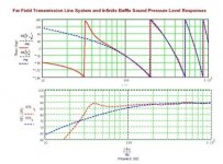
You've got a point there, so I tried a different approach. I used SPLtrace (http://www.pvconsultants.com/audio/frdgroup.htm) to plot the graph of the W172S driver from the Seas specification sheet for this driver. I ended up with two .frd files, one for the woofer, another for the tweeter, which are an accurate plot of the driver output in a anechoic chamber for a given volume (12-liter closed box in this case).
X-over Pro 3 accepts .frd files as input and will give you the option to either normalize the graph to 0dB using a given driver sensitivity (88 and 89dB in this case) or select a frequency band (between x Hz and y Hz) which is flat and level and normalize that to 0dB. I opted for the driver sensitivity option and proceeded to simulate the filter. Again by using the 7-liter closed box design from BassBox Pro 6 as a starting point.
I ended up with the below noted schematic and graph, what surprised me most is that I had to reduce the output of the tweeter by another 4dB, 6dB in total, when compared to the textbook simulation.


How's this for starters? Looks a lot different than before, any other suggestions?
Best regards,
Sander Sassen
http://www.hardwareanalysis.com
You've got a point there, so I tried a different approach. I used SPLtrace (http://www.pvconsultants.com/audio/frdgroup.htm) to plot the graph of the W172S driver from the Seas specification sheet for this driver. I ended up with two .frd files, one for the woofer, another for the tweeter, which are an accurate plot of the driver output in a anechoic chamber for a given volume (12-liter closed box in this case).
X-over Pro 3 accepts .frd files as input and will give you the option to either normalize the graph to 0dB using a given driver sensitivity (88 and 89dB in this case) or select a frequency band (between x Hz and y Hz) which is flat and level and normalize that to 0dB. I opted for the driver sensitivity option and proceeded to simulate the filter. Again by using the 7-liter closed box design from BassBox Pro 6 as a starting point.
I ended up with the below noted schematic and graph, what surprised me most is that I had to reduce the output of the tweeter by another 4dB, 6dB in total, when compared to the textbook simulation.
How's this for starters? Looks a lot different than before, any other suggestions?
Best regards,
Sander Sassen
http://www.hardwareanalysis.com
- Status
- This old topic is closed. If you want to reopen this topic, contact a moderator using the "Report Post" button.
- Home
- Loudspeakers
- Multi-Way
- Seas' T17 and T18 coaxial loudspeakers