Just out of curiousity, when designing an amp, how do you determin what values to make the emitter resistors? and what effects would there be if you altered those values within an amp (not that i would, its just for discussion).
For example. an amp i am working on that has 4 pairs of output devices and uses 5 watt 0.47 ohm emitter resistors. How critical is this value? what if i substituted 0.33 ohm, or 0.70 ohm etc.
What effects would there be if the value was changed. up & down???
again, this is for discussion only.... I found a source for some 0.50 ohm resistors which i figure is close enough to 0.47 to not have any ill effects. but this got me to wondering what effetcs various changes in values would have??
Zc
Higher emitter resistors add a little feedback, helping to keep the quiescent current constant with temperature, and in the case of parallel devices they help share current equally. If you're having difficulty setting a stable bias you may need to increase their value.
They also increase distortion and output impedance, so you want to use the lowest value you can get away with. For BJTs 0.1 is a good choice. I would avoid going below that, or above 0.47. With MOSFETs it's often possible to do without any at all.
They also increase distortion and output impedance, so you want to use the lowest value you can get away with. For BJTs 0.1 is a good choice. I would avoid going below that, or above 0.47. With MOSFETs it's often possible to do without any at all.
If you parallel mosfets, you need source resistors to current share. Not unless you plan to match the darn transistors really very closely. Take it from me as I've had to do this. If you add a little feedback, the source resistance becomes less of a problem. I'm talking 6~12 dB, depending on the circuit.
I'm kinda partial to 0.22 ~ 0.33 ohms for BJT's. Again, depending on the circuit and voltages. The heatsink size also determines how stable an amp is for bias.
-Chris
I'm kinda partial to 0.22 ~ 0.33 ohms for BJT's. Again, depending on the circuit and voltages. The heatsink size also determines how stable an amp is for bias.
-Chris
Lateral MOSFETs will surely be okay without.anatech said:If you parallel mosfets, you need source resistors to current share...
very very good idea
although I had a idea of non emmitter resistor for power BJT a few years ago ,I had no more time to go forward....I found a Japanese very expensive power amp(IIRC,its type is TP ONE..I lost its trade mark) realized my idea a few months ago.
the method of the Japanese amp is applying current mirror in output BJTs( like my initial idea),one power BJT for constant current set and temperature compensation ,other power BJTs(5 pcs?) for SEPP output as mirror
I think that non emmitter resistor is the best,liking the wire is the best 'capacitor'
cheers
X.G.
although I had a idea of non emmitter resistor for power BJT a few years ago
,I had no more time to go forward....I found a Japanese very expensive power amp(IIRC,its type is TP ONE..I lost its trade mark) realized my idea a few months ago.the method of the Japanese amp is applying current mirror in output BJTs( like my initial idea),one power BJT for constant current set and temperature compensation ,other power BJTs(5 pcs?) for SEPP output as mirror
I think that non emmitter resistor is the best,liking the wire is the best 'capacitor'
cheers
X.G.
The Amps i have been repairing are Bass Guitar amps, so the value was probably chooses for stability under extreme conditions VS. Ultimate sound quality.
The value sounded High to me. I am used to seeing 0.1 ohm or 0.33 ohm commonly. so i wondered what effects the values would have.
How does an emitter resistor add feedback to the circuit? I understand how current sharing happens, but not feedback per se.
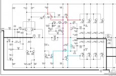
here is the circuit i have been working with.
So far i have 2 of the 3 spare amp channels up and running that i had laying around. I am waiting on parts for the third.
Zc
The value sounded High to me. I am used to seeing 0.1 ohm or 0.33 ohm commonly. so i wondered what effects the values would have.
How does an emitter resistor add feedback to the circuit? I understand how current sharing happens, but not feedback per se.
here is the circuit i have been working with.
So far i have 2 of the 3 spare amp channels up and running that i had laying around. I am waiting on parts for the third.
Zc
Attachments
Mr Evil said:They also increase distortion and output impedance, so you want to use the lowest value you can get away with. For BJTs 0.1 is a good choice. I would avoid going below that, or above 0.47. With MOSFETs it's often possible to do without any at all.
The higher resistors doincrease distortion IIRC from Doug Self, but this seems contrary to logic as they should provide local degenerative feedback, linearising the device.
The output impedance is barely affected because they are within a local feedback loop and within the global feedback loop. The issue is that higher resistors limit the max power output due to their dropping more voltage at high current swings close to the rails.
Be careful using the word MOSFET. Vertical MOSFETs still require resistors, only lateral ones with their -ve tempco at starting low currents can be used without.
Reply
Hi Richie,
We are using n-channel vertical Mosfets without source resistors.
biasing~75mA per device.
environment ambient temp. 35 to 45 degree celcius
4 devices in parallel configuration.
yet no thermal runaway!
excellent current sharing during high current drive
Is it miracle.
cheers,
kanwar
richie00boy said:
Be careful using the word MOSFET. Vertical MOSFETs still require resistors, only lateral ones with their -ve tempco at starting low currents can be used without.
Hi Richie,
We are using n-channel vertical Mosfets without source resistors.
biasing~75mA per device.
environment ambient temp. 35 to 45 degree celcius
4 devices in parallel configuration.
yet no thermal runaway!
excellent current sharing during high current drive
Is it miracle.
cheers,
kanwar
Reply
Hi richie,
No matching , only batch processing.
I think mosfets especially vertical types have positive temperature coefficient not negative , i.e. their RDS increases when the temperature increase and which inturn decreases the current through them.
Would you use a 2000W amp , just for listensing at only 50 Watts!
cheers,
kanwar
richie00boy said:No miracle. Maybe you match the devices beforehand or have tight batches, or because they run hot all the time (when was a PA amp ever not cranked?) the NTC comes into play just in time.
Hi richie,
No matching , only batch processing.
I think mosfets especially vertical types have positive temperature coefficient not negative , i.e. their RDS increases when the temperature increase and which inturn decreases the current through them.
Would you use a 2000W amp , just for listensing at only 50 Watts!
cheers,
kanwar
K-amps said:Hey Zerocool,
Krell uses 1.0 ohm resistors..... go figure.
Hrrrrmmmm, even more reason to scratch my head and wonder!
Zc
Hi kanwar,
You are dancing with the devil. I have experience with what you are doing and can tell you the fets are not sharing current that well. The neg. tempco does seem to start to come in around 50C, so that is what is saving you.
I don't care how many you built that are working, that just means they don't blow up. That's good. The question is on forced current sharing. You would have to put sense resistors in the drains and measure them to prove this.
Case in point. Counterpoint SA-220 has four pairs per channel. Just try and stick non-matched sets in. They will not last. Reason: no source resistors, IRF devices. If you pull the original parts out of one, you will find they are matched unbelieveably tightly. That's what you have to do to get the job done right.
-Chris
- Status
- This old topic is closed. If you want to reopen this topic, contact a moderator using the "Report Post" button.
- Home
- Amplifiers
- Solid State
- Emitter resistor values??