I recently bought an amp kit (a 480) from Dick Smith, and finished making it yesterday. It was my first try, so please excuse any excessive noobieness ") ...
...
Ok, so I am using the suggested transformer and power supply, and they work fine to the bit where I'm supposed to calibrate the trimpot with 2 resistors in place of the fuses. Turning it on though causes it to burn out the 2 resistors.
I noticed the trimpot was currently at 0, and tried again setting it up much higher, but had the same problem.
Basic stuff I've tried - double & triple checking components are all correctly placed/oriented, and checking anything I can with a multimeter. Some results i got that seemed somewhat strange:
With nothing across the fuses (I can't really put anything there atm cause it'll blow up :/), i get +-40V across both fuse holders, ~5V across R5, R4, R13, 0V across R3.
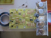
I took photos in the hope they may point out some glaring error, but I'm not much better with the camera than soldering, so try to ignore the blurriness.
... Ok, so I am using the suggested transformer and power supply, and they work fine to the bit where I'm supposed to calibrate the trimpot with 2 resistors in place of the fuses. Turning it on though causes it to burn out the 2 resistors.
I noticed the trimpot was currently at 0, and tried again setting it up much higher, but had the same problem.
Basic stuff I've tried - double & triple checking components are all correctly placed/oriented, and checking anything I can with a multimeter. Some results i got that seemed somewhat strange:
With nothing across the fuses (I can't really put anything there atm cause it'll blow up :/), i get +-40V across both fuse holders, ~5V across R5, R4, R13, 0V across R3.
I took photos in the hope they may point out some glaring error, but I'm not much better with the camera than soldering, so try to ignore the blurriness.
Attachments
Those voltages would be about right. Double check the orientation of Q6 in the heatsink hole - the orientation is opposite to what the leads and pad layout would suggest ie. the base (centre lead) comes from the opposite side of the transistor to join to the pad.
If that is ok, solder a short wire across C & E of Q6, and try the power up again. This wire should reduce output current to zero. If that is ok, double check all components around Q6.
Also make sure there is no connection between the heatsink bracket and any components (case of output transistors, collector of Q7 & Q8 etc).
Cheers
Graeme
hi aquasync,
Have you checked with a multimeter than none of the bolts holding the output transistors in place are shorting to the heatsink. I can't see any insulators on the mounting bolts in the picture.
Also, the speakers shouldn't be connected when testing. I did that once and blew the resistors.
You should really set the bias once you have a proper heatsinks attached. Be very careful just using the aluminium angle.
This is the best site I have seen for further information on the eti 480.
http://www.alphalink.com.au/~cambie/
Good luck
Thanks for the ideas centauri, I'll try that with the Q6. Do I need to have something crossing the fuse holders (my resistors are well and truly trashed now, suppose I need to by some more) for this to work?
As for shorting to the heatsink bracket, I was concerned about this. The kit I got came with these "plastic bushes", which I was supposed to cut in half and put in the holes. I did that, but it didn't seem very adequate. However, I tried to check if they were shorting by putting the multimeter in resistance check mode, and putting a probe on the bracket and on the transistors individually, without getting a reading.
As for not connecting the speakers yet - don't worry, I haven't done that, in fact I'm not entirely sure I know how to connect the output, but I'll figure that out if I can ever get the rest working.
Thanks for the website too, some info there I hadn't seen.
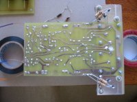
Oh, and here's the bottom picture, (couldn't tack it on before), which may help explain the insulation better than I...
As for shorting to the heatsink bracket, I was concerned about this. The kit I got came with these "plastic bushes", which I was supposed to cut in half and put in the holes. I did that, but it didn't seem very adequate. However, I tried to check if they were shorting by putting the multimeter in resistance check mode, and putting a probe on the bracket and on the transistors individually, without getting a reading.
As for not connecting the speakers yet - don't worry, I haven't done that, in fact I'm not entirely sure I know how to connect the output, but I'll figure that out if I can ever get the rest working.
Thanks for the website too, some info there I hadn't seen.
Oh, and here's the bottom picture, (couldn't tack it on before), which may help explain the insulation better than I...
Attachments
aquasync said:Do I need to have something crossing the fuse holders (my resistors are well and truly trashed now, suppose I need to by some more) for this to work?
Without the fuses / resistors, the voltage across Q6 (collector - emitter) should be somewhere around 1.2 to 1.5V. To test the Q6 shorted trick, then yes, the resistors should be back in.
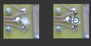
Was just blowing up and trying to enhance your photo of the board underside - not real easy to make out, but Q6 around wrong way could be real possibilty.
Pic shows section of your photo, with proper Q6 orientation.
Cheers
Graeme
Attachments
Just checked the Q6 voltage then, and got 1.6, so thats probably pretty good. Its in the right way, although not easy to tell now with all the heatsink compound, but I definetly had the flat part of the transitor facing towards the pcb.
I'll have to wait a bit to get resistors before I can test out shorting the Q6 (or is it feasible to just link them?).
I can probably coax a better photo out of my camera whn the lighting is better.
I'll have to wait a bit to get resistors before I can test out shorting the Q6 (or is it feasible to just link them?).
I can probably coax a better photo out of my camera whn the lighting is better.
Good - that means the outputs and drivers are all ok - it is the voltage across Q6 that is the problem.
With the resistors AND the short link disconnected, measure the voltage across Q6 again (you said 1.6V before), and vary RV1 full one way then then other and see if the voltage will get below this, say 0.5V or so. Only IF you can get the voltage lower, then retry with the resistors in place. If you cannot get the voltage lower, let us know what range you can get.
Cheers
Graeme
Ok, tried that, and couldn't get it lower than 1.4v, this was at the trimpot's max of around 500 ohms.
I decided to try taking the screw out of Q8, because I noticed that it was conducting to the bracket (Q7 wasn't). No insulation for those 2 is provided, nor any mention of any importance, and further, none of the three leads conducted. I didn't think it would change anything, because it didn't seem that the shell conducted anyway, but after removing the screw, I have since been able to get the voltage over the temporary resistors down to the target range, albeit somehow burning R15 & 17 now.
Maybe something else was responsible.
Retrying the above test gives similar results still.
I decided to try taking the screw out of Q8, because I noticed that it was conducting to the bracket (Q7 wasn't). No insulation for those 2 is provided, nor any mention of any importance, and further, none of the three leads conducted. I didn't think it would change anything, because it didn't seem that the shell conducted anyway, but after removing the screw, I have since been able to get the voltage over the temporary resistors down to the target range, albeit somehow burning R15 & 17 now
.Maybe something else was responsible.
Retrying the above test gives similar results still.
The metal on the back of Q7 & Q8 should be connected to collector (centre pin) and MUST have insulating washers under them.
If R15 and R17 are overheating without the same occurring to R14 & R18, then there is possibly still a short to the heatsink via Q7 or Q8 mounting.
Cheers
Graeme
If R15 and R17 are overheating without the same occurring to R14 & R18, then there is possibly still a short to the heatsink via Q7 or Q8 mounting.
Cheers
Graeme
Just re-reading your posts and looking at your originals photos... Q7 & Q8 do have the required insulator, and the hole through these transistors is insulated, so removing screw SHOULDN'T have made any difference.
Another thought - connect a wire from one of the 0V points to one of the screws bolting the heatsink to the PCB, thereby earthing the heatsink. Then connect another wire between the two input terminals, shorting them together. I notice from your photo the kit has supplied MOSPEC brand output transistors, and the high currents could be due to supersonic oscillation - a real possiblity with these transistors. The original design used Motorola transistors and was very stable, however I have seen some of these amps go unstable with questionable transistors. When the kit is eventually installed in its case, the heatsink will then be earthed, and the input will not be open - hopefully keeping it stable.
Cheers
Graeme
The Q7 & 8 do have the insulating washer, but what wasn't provided were extra plastic bushes, and seeing as there was some discrepancy in the hole layout between the pcb & bracket, those screws touched the bracket on the way down.
I have since got some extra ones (plastic bushes) from an old broken amp given to me, and so hopefully that won't be a problem anymore.
After I fix that, I'll retest the voltages, and try your recent suggestions.
Thanks for all the help by the way!
I have since got some extra ones (plastic bushes) from an old broken amp given to me, and so hopefully that won't be a problem anymore.
After I fix that, I'll retest the voltages, and try your recent suggestions.
Thanks for all the help by the way!
Close examination of the Q7 & Q8 transistors will show that the hole itself is well insulated, and the metal on the rear is away from the hole. Therefore it does not matter that the screws themselves touch the heatsink.
My main concern at the moment is instability, so earthing the heatsink and shorting the input should help that.
Cheers
Graeme
My main concern at the moment is instability, so earthing the heatsink and shorting the input should help that.
Cheers
Graeme
Ok, I resoldered the 4 links on the bottom that were bothering me, fixed all screws, triple checked for shorting, earthed the bracket anyway, and shorted the input (phew!).
I also had to buy new resistors again, dick smith are phasing out there 1/2 watts, and had none in stock (wtf!?), and with a choice of 1/4 & 1, I assumed 1 would be ok, perhaps giving me a few seconds extra before burning.
So, with all that, the voltage was settable, and some temporary wires showed some audio amplification in action; yeah !
I'm not sure my cables were set up right, the instructions don't really say (and I'm not sure if it matters), which input should get the primary one (the centre coming from my rca socket), and which should get the outside / shielding. Similarly, with the outputs, I stuck the main output one to the centre, and another 0v one to its outside, although as I understand it, a mis-wiring here would only change the phase of the speaker. That still leaves another 0v, I guess I'm supposed to earth that one? I post a photo of my connections later, just to check that I'm not doing something completely stupid.
I had a few general questions about the amp that you may know; it's class AB as I understand, so a quieter signal means it uses less power right? Also, is there a recommended pre amplification signal strength; like do you think a pre-amp would be required for input from a soundcard, do reach its full potential?
Thanks again for all the help with the troubleshooting. I'd probably have had to have trashed this otherwise.
I also had to buy new resistors again, dick smith are phasing out there 1/2 watts, and had none in stock (wtf!?), and with a choice of 1/4 & 1, I assumed 1 would be ok, perhaps giving me a few seconds extra before burning
.So, with all that, the voltage was settable, and some temporary wires showed some audio amplification in action; yeah !
I'm not sure my cables were set up right, the instructions don't really say (and I'm not sure if it matters), which input should get the primary one (the centre coming from my rca socket), and which should get the outside / shielding. Similarly, with the outputs, I stuck the main output one to the centre, and another 0v one to its outside, although as I understand it, a mis-wiring here would only change the phase of the speaker. That still leaves another 0v, I guess I'm supposed to earth that one? I post a photo of my connections later, just to check that I'm not doing something completely stupid.
I had a few general questions about the amp that you may know; it's class AB as I understand, so a quieter signal means it uses less power right? Also, is there a recommended pre amplification signal strength; like do you think a pre-amp would be required for input from a soundcard, do reach its full potential?
Thanks again for all the help with the troubleshooting. I'd probably have had to have trashed this otherwise.
Glad to hear its finally going
Regarding the wiring, input "hot" goes to pin closest to C1, and input shield goes to the pin next to it (connected to R3).
3 earth pins are provided, and due to layout, the order of these is not critical. One is your power supply ground, another is speaker ground, and the other could be used to ground the case if need be.
Regarding earth wiring, though this amp module was designed this way, I don't like the idea of connecting speaker ground to the amp board, as speaker currents can modulate the amp ground and cause distortion or instability. I normally prefer to see speaker and case grounds returned back to the ground of the power supply capacitors.
A soundcard should provide enough level to drive this fine, but I would put a volume control between the two.
Cheers
Graeme
- Status
- This old topic is closed. If you want to reopen this topic, contact a moderator using the "Report Post" button.
- Home
- Amplifiers
- Solid State
- eti 480 build problems