Has anyone tried national's single supply schematic for either of these chips? I'm looking to build a 2 channel amplifier for computer speakers to actually put into the speaker enclosure with the heatsinks making up the back of one of the speakers.
I'd prefer the lm1876, but I am looking for a minimal design, mostly because it makes the PCB layout, and the LM1876 needs the transistor and a couple extra components for the mute function.
Is there a minimal design out there for either of those chips? Ideally, I'd like to use p2p construction, but the circuit looks too complex to do that.
The reason I want to do single supply is save space in the enclosure, and a transformer takes up a heck of a lot more space then a wall wart (I know, its nowhere near ideal, but these are computer speakers..)
Thanks,
Adam
Adam M. said:The reason I want to do single supply is save space in the enclosure, and a transformer takes up a heck of a lot more space then a wall wart (I know, its nowhere near ideal, but these are computer speakers..)
Thanks,
Adam
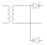
If the wall wart has AC output, you could create dual rails.
See the attached image.
This is not ideal, but it would work.
Of course you would have to add capacitors and snubbers etc.
")
Attachments
The single supply is very easy. Just create a virtual ground using two 2.2k resistors (or even anything close to that, really), and then use the same schematic you would for a dual supply. I did it a few weeks ago with an lm1876 and it works like a charm.
I'll actually probably use this from now on, just because I only have to use one bridge rectifier and I didn't notice any difference in sound.
I'll actually probably use this from now on, just because I only have to use one bridge rectifier and I didn't notice any difference in sound.
mateo88 said:The single supply is very easy. Just create a virtual ground using two 2.2k resistors (or even anything close to that, really), and then use the same schematic you would for a dual supply. I did it a few weeks ago with an lm1876 and it works like a charm.
I'll actually probably use this from now on, just because I only have to use one bridge rectifier and I didn't notice any difference in sound.
In that case, how do you get a true ground? The virtual ground will reference the rail voltages properly, but the virtual ground will still be 1/2 the supply voltage above true ground. Is this not a problem, and you just keep virtual ground an true ground seperate? I would think that would create a DC offset on the output.
Also, what kind of power rating would the resistors need? I don't see much current going through those resistors, but want to make sure.
Thanks,
Adam
I'm not sure if I get what you're saying exactly, but there is no dc offset created by using a virtual ground. I suppose it would screw something up if you grounded the circuit via the ground pin on a power outlet, but otherwise it will be fine. Just make the virtual ground and pretend like you're building the amp with a dual supply.
I used 1/4 watt 2.2k resistors, but if you go too much lower than that you should probably use 1/2 watt to be on the safe side.
Good luck! 
I used 1/4 watt 2.2k resistors, but if you go too much lower than that you should probably use 1/2 watt to be on the safe side.
Good luck!
The circuit, mentioned by Squadra in reply 4 of this thread, is a voltage doubler circuit (Greinacher).
Just add the two necessary bypass caps, and you have this circuit.
It is not good advice to use voltage doubler for a gainclone psu, imho. Drawing a big current causes big ripple (and dont forget the voltage drop, using the small tranny inside the wall wart!).
This circuit is very suitable as a PSU for a class A tube buffer or other Class-A pres, drawing a few mA's.
I use it for my tube buffered gainclones, easily delivering +/-60V out of common print-trannies
BTW: for PSU simulations, just search the net for Duncan's Amp tools and download for free the PSU Designer, a very neat tool.
Franz
P.S.
As you can see, I have a perfect functioning space bar, as I opened my keyboard and removed some tobacco (...) between the contacts...
pinkmouse said:Doesn't the data sheet of the 1875 have a schema for a single supply amp?
yes it does.
dave
Attachments
mateo88 said:The single supply is very easy. Just create a virtual ground using two 2.2k resistors (or even anything close to that, really), and then use the same schematic you would for a dual supply. I did it a few weeks ago with an lm1876 and it works like a charm.
Are you putting the o/p through a big cap ?
If not, how are connecting the speaker return ?
normally it would go to the earth that this arrangement is high impedance.
mike
To use single supply, you need both input and output caps. The signal is referenced to ground on the outside of the caps, but referenced to 1/2V+ inside the caps (on the device side of the caps).
Yes, there is a DC offset on the output of the device and that is why you need an output cap. The cap removes the DC offset and the AC part of the signal is now referenced to ground.
Yes, there is a DC offset on the output of the device and that is why you need an output cap. The cap removes the DC offset and the AC part of the signal is now referenced to ground.
- Status
- This old topic is closed. If you want to reopen this topic, contact a moderator using the "Report Post" button.
- Home
- Amplifiers
- Chip Amps
- LM1875/lm1876 single supply?