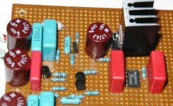
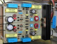
Mosfet and Jfet +15 volt regulator. 2SK170 diffamp with 3mA 2SK170 CCS drain load. ZVP3310 mosfet follower drives IRF510 mosfet follower output. PMI REF01 10 volt voltage reference with RC input and output filters. WIMA and RIFA polypropylene and Seimens Electrolytic caps. Two +15 regulators will be tied together at outputs for +/- 15 outputs. Inputs are seperate 25V CLC filtered supplies with snubbered soft recovery diodes.
Attachments
Getting ready for Dorkus' preamp?
I don't think so........ Actually I will use it for preamp circuit I am designing. Designing reglators is as fun as audio circuits and is probably as important to the sound. If it sounds OK I will post schematic if anyone is interested.
H.H.
I don't think so........ Actually I will use it for preamp circuit I am designing. Designing reglators is as fun as audio circuits and is probably as important to the sound. If it sounds OK I will post schematic if anyone is interested.
H.H.
I'm very interested. I'll bet others are as well. Hey, how about a picture of the underside? I'm also interested in stealing ideas on how to build stuff. Thanks in advance, Harry.HarryHaller said:If it sounds OK I will post schematic if anyone is interested.
Jean said:Awwww
If someone would just tell me where you guys purchase WIMA and RIFA caps ?I would like to my circuits to look nice also and cheap ceramic caps are so ugly .
ELFA in Sweden has. They sell also on export. Some parts are in english, the rest is in swedish but I can help if wonder about something.
Capacitor is "kondensator" in swedish and search is "sök"
http://www.elfa.se
Designing reglators is as fun as audio circuits and is probably as important to the sound. If it sounds OK I will post schematic if anyone is interested.
Couldn't agree more.
Just abuot to test a low-drop-out regulator for my Pass ClassA amp.
Jean said:Awwww
If someone would just tell me where you guys purchase WIMA and RIFA caps ?
All my Rifa and Wima caps are surplus, bought locally. I've got quite a selection of Wima MKS 10, 2,2uF/250V. If somebody interested I might spare few at $3.
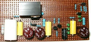
Fet regulator circuit version 2
Changes from first version:
LED voltage refences biased by jfet current source fet, 10K resistor to ground for drain load for jfet diff amp, mosfet current source for bias for 10K resistor and jfet drain current, F-Dyne polypropylene and foil 0.1 uF caps, 1Meg and 3uF filter for voltage ref, copper foil tape ground trace and better layout in terms of decoupling and gound current return paths.
Attachments
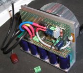
Here is the power supply (shown withou pre-regulation) for my next Pearl. I own the layout but not the design, so I cannot share unfortunately. This is going into some commercial equipment but I am of course free to use it myself.
Topology: +-HV (up to 90V) and +-LV (set up for less than 30V).
The reason the two are different is amongst other things the inclusion of op-amp power from source on the HV version.
Design optimized for short sense resistances to op-amp and extremely short signal path from output of op-amp.
Petter
but I am of course free to use it myself.Topology: +-HV (up to 90V) and +-LV (set up for less than 30V).
The reason the two are different is amongst other things the inclusion of op-amp power from source on the HV version.
Design optimized for short sense resistances to op-amp and extremely short signal path from output of op-amp.
Petter
Attachments
Re: Why no schematics?
I absolutely agree!
Tomorrow is another day. I will see what I can do. - -
Hi Ian,Ian Macmillan said:Many of the above are great looking layouts, but me, I would prefer to see schematics. These are much easier to debate
Ian.
I absolutely agree!
Tomorrow is another day. I will see what I can do.
- - - Status
- This old topic is closed. If you want to reopen this topic, contact a moderator using the "Report Post" button.
- Home
- Amplifiers
- Solid State
- Fet regulator circuit