I know it has been done, even with audiofile grade amplifiers, but I want to know what are the special characteristics of the SMPS's for audio amps. I'm pretty much a novice with SMPS's, I only know the basics, but I have this Motorola handbook on voltage regulators (including switch mode) at home, and I thought about using a switch mode power supply for my future Quad 707, I think it would be a right place to use it, since the amp has an output rating of 240 Watts. Can anyone help with some info?
The first thing that springs to mind is noise. SMPSs will have switching noise on the rails, and will radiate it too. For audio, this needs to be as low in amplitude as possible within the audio band. This means very good filtering and shielding, and as high a switching frequency as possible. Things like efficiency and regulation are of lesser importance for most audio applications.
Yes, but small is coolMr Evil said:Things like efficiency and regulation are of lesser importance for most audio applications.
 I saw once this class-D amp with a SMPS, it had an output rating of 700W if I recall correctly and it had only a few centimeters of height.
The noise issue can be overcome I think, currently the switching frequencies are high enough. But still intermodulation can become a problem.
One problem with SMPS's that someone mentioned once is that the common ones are not fast enough to cope with the dynamics (and corresponding drawn current varriations) found in music. Is that correct?
'Noise' is a classic misconception about SMPS
Speaking properly, there is no noise in SMPS, since noise by definition is a signal of random nature and what SMPS produce on their output is periodic 'ripple' as any 50/60Hz supply. We could call this 'conducted ripple'
This ripple is usually a sawtooth waveform and it may have some RF ringing on transients [on the peak and valley of the sawtooth cycle]. There's not much difference from 50/60Hz supplies, except the ripple frequency is about 1000 times higher
As in 50/60Hz supplies, ripple is easily filtered with pi filters and it may be attenuated as desired [even below noise floor], but with the advantage of size since 100Khz pi filters are much smaller and cheaper than 100Hz pi filters
There is also 'radiated ripple' like in any 50/60Hz supply. This radiation happens both due to quick changes in electric fields and quick changes in magnetic fields in the SMPS circuit [as in any non-linear circuit with diodes or switches]
Electric fields are shielded by just mounting the SMPS inside a grounded metal case and it's production may be reduced by means of optimized PCB layout [reducing the lenght and shielding high dV/dt tracks]
Magnetic fields get only about 20dB attenuation with metal cases, but it's production may be also reduced by means of proper layout [essentially reducing the area of high dI/dt PCB loops]
There are also field-cancellation layout techniques based on dipoles or multi-poles
Ringing at switching transients is produced by parasitistic resonance of capacitive/inductive elements in the circuit [unexpected RLC resonators excited during switching transients], like parasitistic capacitances of MOSFETs, parasitistic inductances of PCB traces and parasitistic self-inductances/capacitances of windings. [Increasing or decreasing parasitistic R may damp the oscillation but it's not allways practical]
Using bipolar transistors or IGBTs causes a dramatic reduction of ringing since they show capacitances an order of magnitude smaller than MOSFETs and have inherently limited switching rise and fall speeds as opposed to MOSFETs, reducing dI/dt and dV/dt
Schottky diodes and SiC diodes also reduce ringing dramatically since Schottkys show no reverse-recovery period and SiC diodes show very small reverse recovery. Reverse recovery is allways a pain in non-transformer-coupled buck and boost converters and the source of most radiated ripple in these converters
Radiated ripple atenuates 12dB every time the distance is doubled, so placing the SMPS away from small signal equipment is also useful. Anyway, ambient noise usually dominates over SMPS far-field radiated ripple
A final note : Paralelling different kinds of capacitors, like electrolytics with ceramics, ceramics with films, electrolytics with films, etc... Usually produces high Q resonant RLC networks and lots of ringing. Each case must be studied carefully before paralelling different type of capacitors in an SMPS, since it usually increases ringing instead of reducing it!!!
This is also true for audio circuits

Audio power amplifiers do not have a constant current draw, the peaks are (rough estimate) 10x higher than the average current. Most SMPS's cannot deliver (much) larger peaks than their average rated currents for a sufficiently long time, so these must be sized based on the expected peak currents. Therefore the average current capability will be unnecessarily large. The rated output power of the SMPS would be about two times the amplifier power output for a class B or D amplifier.
Last edited:
But the same goes for linear power supplies and transformers, powering a class AB amplifier of about 1kW rated continual output power would still demand a transformer and filter capacitors that can sustain the peaks so about 1.5kW or maybe bit more.
Only SMPS even if designed with double the rated power is still smaller and more compact not to mention that due to the much higher frequency the filter caps don't sag in voltage as much as the lower frequency (50/60hz) large filter caps from a mains transformer for the same amount of peak power demand for indentical power rated supplies.
Only SMPS even if designed with double the rated power is still smaller and more compact not to mention that due to the much higher frequency the filter caps don't sag in voltage as much as the lower frequency (50/60hz) large filter caps from a mains transformer for the same amount of peak power demand for indentical power rated supplies.
A final note : Paralelling different kinds of capacitors, like electrolytics with ceramics, ceramics with films, electrolytics with films, etc... Usually produces high Q resonant RLC networks and lots of ringing. Each case must be studied carefully before paralelling different type of capacitors in an SMPS, since it usually increases ringing instead of reducing it!!!
This is also true for audio circuits
Any advice as to how measure / verify such increased ringing?
There are three gotchas from my experience using off-the-shelf SMPS modules.
First is that they aren’t immune to 50Hz. They rectify the mains, filter it, then chop that at above audio frequency. The filtering on the rectified mains is only enough to meet their ripple specs, which are generally pretty bad. So the 50Hz is present at the transformer primary, and makes it all the way through to the output. You can often use an external rectifier and your own filter cap (though this will be at 450V), to reduce the 50Hz. Or even a capacitor multiplier on the input.
Second is that they can have components of their switching at audio frequency when under low load. Many SMPS “burp” when lightly loaded. They switch on briefly to charge their output cap, then shut down. This greatly increases efficiency, but is very audible. Often you’ll need to ensure the load is high enough to prevent that.
Third is you can’t just throw capacitance at the output to shut them up. That will just result in a supply that refuses to start, due to hitting current limit when trying to charge the capacitance. They usually have a output capacitance limit in their specs.
Best way to shut up a SMPS is to put a linear regulator or capacitance multiplier after it, with high ripple rejection through the whole audio band.
Nice high signal to noise ratio on this thread.
Eva, you should write textbooks. And suzyj said so much in so few words.
I clicked this thread expecting the typical dogma based proofs by vigorous assertion and instead find great illuminations into the issues and tradeoffs. Think about those issues and it becomes clear why it is the companies with engineering depth that succeed in using SMPS with high-end amps.
I am almost finished with the first build of my new amp and the SMPS supply. It is my first real go at offline SM supply. Anyway, very interesting what Suzyj is stating about the mains ripple leaking into the output, my VAS uses a small current, higher tier voltage supply and it is an unregulated auxiliary output. I suspected it could be modulated from the primary side. Nice to hear more knowledgeable people to confirm these issues. It certainly shows a 120Hz ripple (60 cycles here). Extra low frequency filtering is needed.
I am using a PQ32/30 core, half bridge assymetric. I like the POT-like shielding of the windings.
I also suspect that using the offline supply to power 12V, and then use toroid and push pull step up converter would eliminate the mains ripple components.....at the expense of complexity and a bit of efficiency. Lol
There are three gotchas from my experience using off-the-shelf SMPS modules.
First is that they aren’t immune to 50Hz. They rectify the mains, filter it, then chop that at above audio frequency. The filtering on the rectified mains is only enough to meet their ripple specs, which are generally pretty bad. So the 50Hz is present at the transformer primary, and makes it all the way through to the output. You can often use an external rectifier and your own filter cap (though this will be at 450V), to reduce the 50Hz. Or even a capacitor multiplier on the input.
Second is that they can have components of their switching at audio frequency when under low load. Many SMPS “burp” when lightly loaded. They switch on briefly to charge their output cap, then shut down. This greatly increases efficiency, but is very audible. Often you’ll need to ensure the load is high enough to prevent that.
Third is you can’t just throw capacitance at the output to shut them up. That will just result in a supply that refuses to start, due to hitting current limit when trying to charge the capacitance. They usually have a output capacitance limit in their specs.
Best way to shut up a SMPS is to put a linear regulator or capacitance multiplier after it, with high ripple rejection through the whole audio band.
All this is true if you consider an unregulated smps, like a fixed frequency LLC converter without preceeding PFC. The 100Hz ripple is in the same ballpark as with conventional transformer - bridge rectifier supply, which worked for decades decently with decent amps.
But the off-the shelf meanwell smps and the likes are well regulated so there is quite little 100Hz ripple at the output, no need for a linear reg or other fancy stuff.
Last edited:
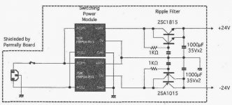
Would this ripple filter work?
Yes, that ripple filter would work. The current sharing of the parallel transistors should be improved with emitter resistors and the ripple tolerance is in the order of some 600mVpp only. It is a low power supply as each transistor can handle a maximum of 150mA.
The circuit needs modification for higher power.
NB: Evidently, the filter is not without a voltage drop (and power loss). 24V in will leave some 23.2V out.
Last edited:
Member
Joined 2009
Paid Member
Using bipolar transistors or IGBTs causes a dramatic reduction of ringing since they show capacitances an order of magnitude smaller than MOSFETs and have inherently limited switching rise and fall speeds as opposed to MOSFETs, reducing dI/dt and dV/dt
Hi Eva,
Is this still true of current production IGBT's and MOSFETs ?
Have you guys seen this:
https://www.diyaudio.com/forums/vendor-s-bazaar/281413-audio-smps-units-sale-14.html#post5939302
Jan
https://www.diyaudio.com/forums/vendor-s-bazaar/281413-audio-smps-units-sale-14.html#post5939302
Jan
Last edited:
Any advice as to how measure / verify such increased ringing?
Approach #1 is network analysis.
Low cost network analysis may be achieved with prototype geometrically representative of final design, square wave generator of suitable rise time, square wave injection through suitable impedance [such as to make injection inductance negligible], and voltage waveform analysis through oscilloscope of suitable bandwidth and resolution as to overcome attenuation due to injection impedance. If square wave with rise times exceeding speed required by source and load looks smooth, filter is good.
High cost network analysis involves equipment specifically designed for doing so. Often five digit price.
Approach #2 is network heuristics.
Each component package has characteristic inductance. PCB traces, wires or any conductor geometry has characteristic inductance and capacitance. Each capacitor type and size has characteristic ESR to capacitance / size ratio. This data can be derived from approach #1 applied to a representative set of components and annotated in proper Engineering Notes, allowing to make an accurate first guess for new designs or modifications. There is a wide selection of software to simulate RLC networks. From latest LTSpice to old Electronics Workbench.
Initial rule of thumb, which can and should be verified by every experimenter independently, is that 1nH/mm is an accurate first guess for component lead inductance and PCB track or wire inductance (no ground plane or shield). This figure can improve to 1nH per few cm with close ground plane as in 4+ layer PCB.
Last edited:
'Noise' is a classic misconception about SMPS
Speaking properly, there is no noise in SMPS, since noise by definition is a signal of random nature and what SMPS produce on their output is periodic 'ripple' as any 50/60Hz supply. We could call this 'conducted ripple'
This ripple is usually a sawtooth waveform and it may have some RF ringing on transients [on the peak and valley of the sawtooth cycle]. There's not much difference from 50/60Hz supplies, except the ripple frequency is about 1000 times higher
As in 50/60Hz supplies, ripple is easily filtered with pi filters and it may be attenuated as desired [even below noise floor], but with the advantage of size since 100Khz pi filters are much smaller and cheaper than 100Hz pi filters
There is also 'radiated ripple' like in any 50/60Hz supply. This radiation happens both due to quick changes in electric fields and quick changes in magnetic fields in the SMPS circuit [as in any non-linear circuit with diodes or switches]
Electric fields are shielded by just mounting the SMPS inside a grounded metal case and it's production may be reduced by means of optimized PCB layout [reducing the lenght and shielding high dV/dt tracks]
Magnetic fields get only about 20dB attenuation with metal cases, but it's production may be also reduced by means of proper layout [essentially reducing the area of high dI/dt PCB loops]
There are also field-cancellation layout techniques based on dipoles or multi-poles
Ringing at switching transients is produced by parasitistic resonance of capacitive/inductive elements in the circuit [unexpected RLC resonators excited during switching transients], like parasitistic capacitances of MOSFETs, parasitistic inductances of PCB traces and parasitistic self-inductances/capacitances of windings. [Increasing or decreasing parasitistic R may damp the oscillation but it's not allways practical]
Using bipolar transistors or IGBTs causes a dramatic reduction of ringing since they show capacitances an order of magnitude smaller than MOSFETs and have inherently limited switching rise and fall speeds as opposed to MOSFETs, reducing dI/dt and dV/dt
Schottky diodes and SiC diodes also reduce ringing dramatically since Schottkys show no reverse-recovery period and SiC diodes show very small reverse recovery. Reverse recovery is allways a pain in non-transformer-coupled buck and boost converters and the source of most radiated ripple in these converters
Radiated ripple atenuates 12dB every time the distance is doubled, so placing the SMPS away from small signal equipment is also useful. Anyway, ambient noise usually dominates over SMPS far-field radiated ripple
A final note : Paralelling different kinds of capacitors, like electrolytics with ceramics, ceramics with films, electrolytics with films, etc... Usually produces high Q resonant RLC networks and lots of ringing. Each case must be studied carefully before paralelling different type of capacitors in an SMPS, since it usually increases ringing instead of reducing it!!!
This is also true for audio circuits
Thank you for this wonderful write up (reading it after almost a decade 😅 but still feels relevant). SiCFETs are more common these days than it was earlier and evolution of mobile phone has made a lot of great things happen in the pocket sized devices space.
My two pence (cents).
So far I've investigated boost converters for powering an OTL headphone tube amp. Getting to about 2-300W you will find that things start getting a little problematic for the simple topologies.
There's a large trade off between cost, size and performance - just like a linear supply. Especially as current increases as an output at high voltage, simply put the higher the power the more the problems.
The lower the frequency the more likely the switching noise (yes it's noise as it's undesired signal) will appear, along with (sub)harmonics, in the audio spectrum. The larger the size of components (larger flux needed for each pulse) which means simpler components and cheaper ones.
Bear in mind a hammond mH 20+A inductor ends up weighing 32Kg.
Higher frequency shifts the noise up, making it easier to be filtered but at the cost that caps need careful selection to work correctly (ESR varies with frequency). The higher switching causes more interference but reduces the cost of the inductors etc.
Next up is it a CCM or DCM? Does the inductor current hit zero? Hitting zero, just like a (A)B class amp, causes harmonics thus more noise.
Current limiting is actually the easy bit - a sensing resistor or coil allows for the current to be limited and thus the total power.
Minimum power is the problem. If the system is changing it's PWM duty cycle, then the frequency spectrum of the noise changes, If the system starts blanking/skipping pulses to reduce power then that frequency drops further and you will very likely find it in the top end of the audio spectrum (especially with subharmonics from DCM).
Additionally a lot of systems pulse the mosfet to switch it OFF. By default the mosfet is conducting. So a zerio-minimum power situation means the mosfet is conducting heavily at full load. RDSon and junction temperature becomes the issue - check your safe operating area and you will see you're now probably in trouble at 200-300W.
Also running at >50% duty cycle then has stability issues that need managing this is where charge/discharge cycle starts wandering due to disruptions of the load etc.
MOSFET gate and overall capacitance starts causing problems at higher switching frequencies.
It's a misconception that a SMPS can't cope with high capacitance or inductive loads. The truth is that they have made a decision that it is more efficient (hence they can claim better efficiency) to drive a resistive load. That means more sales and less mainstream support for capacitive/inductive loads.
A boost converter with current sense and a top mosfet will simply limit the current being supplied, acting as a soft start for the caps. Without the top mosfet the caps simply draw full Vin through the inductor so that acts to softitart but only by the inductor acting as a large resistor! More mosfets = higher cost.. so decisions are made to keep costs down.
Now we're not looking at the impact to the external system - the main supply. noise filtering needs to be supplied not only for the sanity of the house but also the supplementary supplies that power the SMPS control circuits. For example well used boost converter ICs Vcc go straight into the gate drive totem so noise from the mosfet travels up through the inductor, through to Vin and then into Vcc, and back into the mosfet which then causes noise that then traveled back through the mosfet... inductor.. Vin.. Vcc.. and the cycle continues. Bypassing and filtering backwards.. is your friend.
You find you're paralleling caps to prevent heating, the effect that although each smaller cap has a higher ESR than the large one, in parallel the they will have a lower ESR and support a higher current rate = higher inrush and higher dI/dt = higher frequency noise.
Lots more but I'm current exploring a hybrid OTS with a post booster using a half bridge with a full bridge rectifier on the HT side.
- Home
- Amplifiers
- Power Supplies
- SMPS for Hi-Fi?