I just ordered one of these regs.
http://www.lcaudio.dk/com/dcreg1.jpg
Looking at the schematic I see some possibilities for further improvement of the noise performance.
http://www.lcaudio.dk/com/dcreg.gif
As I am merely an armchair designer, I am looking your opinions on my ideas:
- Bypassing D20 (led) with 47 uF in order to filter out led noise;
- Adding a cap across the lower leg of the potmeter ( from opamp in+ to ground) to create some lowpass filtering, in order to filter out zenernoise;
- Decreasing noise gain of both opamps by bypassing R39 and R36 with appropriate cap, some 22 uF;
- Adding power supply bypasses (10-22 nF) for the opamp;
- ??
What do you think? Will this work and improve the performance of this circuit?
thanks,
Abo
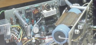
By the way: Does anybody know what that thing is across the higher leg of R35?
http://www.lcaudio.dk/com/dcreg1.jpg
Looking at the schematic I see some possibilities for further improvement of the noise performance.
http://www.lcaudio.dk/com/dcreg.gif
As I am merely an armchair designer, I am looking your opinions on my ideas:
- Bypassing D20 (led) with 47 uF in order to filter out led noise;
- Adding a cap across the lower leg of the potmeter ( from opamp in+ to ground) to create some lowpass filtering, in order to filter out zenernoise;
- Decreasing noise gain of both opamps by bypassing R39 and R36 with appropriate cap, some 22 uF;
- Adding power supply bypasses (10-22 nF) for the opamp;
- ??
What do you think? Will this work and improve the performance of this circuit?
thanks,
Abo
By the way: Does anybody know what that thing is across the higher leg of R35?
Hi
That thing on R35 is a bubble to enable the regulator to be used at full voltage with no trimmer.
I personally don't subscribe to filtering out Zener or LED noise with caps, as they will not remove noise, merely move the noise to lower frequency zones. Better is to use a low noise reference, that don't need filtering.
Cheers
LC
Lars Clausen said:Better is to use a low noise reference, that don't need filtering.
Please send that design improvement to the designer
") It could have been implemented in the design.
It could have been implemented in the design.At least the decoupling of the opamp supply lines won't hurt.
Lars Clausen said:I personally don't subscribe to filtering out Zener or LED noise with caps, as they will not remove noise, merely move the noise to lower frequency zones.
??
Questions
Hi Abo,
I would be more inclined to ask:
Why MOSFETs as the pass-element?.
Why a constant current source for the reference comprised of two transistors, three resistors and a blue LED?.
Why the antiquated NE5532 as the opamp? Then.....
Just some questions.
ABO said:Surely someone must have ideas?
Hi Abo,
I would be more inclined to ask:
Why MOSFETs as the pass-element?.
Why a constant current source for the reference comprised of two transistors, three resistors and a blue LED?.
Why the antiquated NE5532 as the opamp? Then.....
Just some questions.
Elso: Sorry i didn't see your questions until now. Here are some answers for you:
1..MOSFET's are perfect a pass elements, as they require no drive current, and will stand high loads. I see no drawbacks of using MOSFET's, the highest pole of the regulator loop is handled by capacitors, so a particularly high loop speed is not required.
2..The constant current source, for which the base current is pre regulated using the LED as a sort of Zener shunt, gives the Zener perfect working conditions. Free of the load regulations found in other types of low noise regulators taking the Zener current from the output of the positive regulator, and thus allows the reference to fluctuate when the regulator loop reacts to changing loads. (If present).
3..Well the NE5532 may be old, but as i often tell my employees, just because something (or someone) is old, doesn't mean it's useless. The NE5532 is very low noise (definitely not the bottleneck in any regulator, the Zener will most probably have 100 times higher noise than the op-amp) In this case the Zener has typ 7 uV RMS noise, (Max 100 uV) while the NE5532 has just around 30 nV RMS input related noise.
So it makes no sense to use a lower noise op-amp.
And it has one great advantage over any ultra low noise opamp: it can operate on +/- 22V (Philips brand).
I hope this answers your questions.
All the best from
Lars
1..MOSFET's are perfect a pass elements, as they require no drive current, and will stand high loads. I see no drawbacks of using MOSFET's, the highest pole of the regulator loop is handled by capacitors, so a particularly high loop speed is not required.
2..The constant current source, for which the base current is pre regulated using the LED as a sort of Zener shunt, gives the Zener perfect working conditions. Free of the load regulations found in other types of low noise regulators taking the Zener current from the output of the positive regulator, and thus allows the reference to fluctuate when the regulator loop reacts to changing loads. (If present).
3..Well the NE5532 may be old, but as i often tell my employees, just because something (or someone) is old, doesn't mean it's useless.
The NE5532 is very low noise (definitely not the bottleneck in any regulator, the Zener will most probably have 100 times higher noise than the op-amp) In this case the Zener has typ 7 uV RMS noise, (Max 100 uV) while the NE5532 has just around 30 nV RMS input related noise. So it makes no sense to use a lower noise op-amp.
And it has one great advantage over any ultra low noise opamp: it can operate on +/- 22V (Philips brand).
I hope this answers your questions.
All the best from
Lars
Lars Clausen said:Elso: Sorry i didn't see your questions until now. Here are some answers for you:
1..MOSFET's are perfect a pass elements, as they require no drive current, and will stand high loads. I see no drawbacks of using MOSFET's, the highest pole of the regulator loop is handled by capacitors, so a particularly high loop speed is not required.
2..The constant current source, for which the base current is pre regulated using the LED as a sort of Zener shunt, gives the Zener perfect working conditions. Free of the load regulations found in other types of low noise regulators taking the Zener current from the output of the positive regulator, and thus allows the reference to fluctuate when the regulator loop reacts to changing loads. (If present).
3..Well the NE5532 may be old, but as i often tell my employees, just because something (or someone) is old, doesn't mean it's useless.
So it makes no sense to use a lower noise op-amp.
And it has one great advantage over any ultra low noise opamp: it can operate on +/- 22V (Philips brand).
I hope this answers your questions.
All the best from
Lars
Lars,Originally by MalichiConstant
I think most of the choices are for less $$. The choice of high current mosfets is a mystery to me since at currents of a few 10s of milliamps the transconductance is very low and the output impedance VERY high. Figure 4 volts turn on for the mosfets and a couple of volts overhead from the op amp output and the minimum supply voltage for the op amp is about Vout plus 6 volts or about 20 volts. This is about the highest recommended supply voltage for the NE5532 (and higher than most op amp supply limits). Anyone wanting +/15 volts out of this design topology is out of luck. Using a faster op amp or lower current mosfets without gate resistors is asking for trouble.
IMO this a very poor implementation for a low current op amp based regulator for a commercial regulator. The lack of filtering for the LM 329 defies logic other than cost savings run amuck. Spend another 10 cents for a cap and resistor if you are going to call it a low noise regulator.
I am well aware that a constant current source improves the performance of the LM329, as I am using it all the time in my supply for the TDA1543. I was merely asking why this particular current source for the reference. Why not a red LED and a transistor or two FETs or simply a J505?
Your claim that the extended supply range of the NE5532 (+/-22V) is an advantage is invalid as you are using the opamp on a + or - 20V single supply to ground. 20V total span. So any low noise opamp designed for a regular +/- 15V supply will do.
It is intriguing that you are using the suggested noise filtering by MalichiConstant in you XO-3 circuit. (R14 and C7). I am afraid you are confusing noise filtering with noise shifting by a Delta-Sigma DAC. I never experienced an increase in low frequency noise when applying low-pass noise filtering.
Last question why not using a dual-tracking regulator? (Horowitz page 351)
MalichiConstant,
As Lars is running the opamps single supply he could use a higher supply voltage for more drive. This will increase the dropout voltage. But the dropout voltage of the regulator is already a hefty 7V.
Elso Kwak said:
Lars,
I am well aware that a constant current source improves the performance of the LM329, as I am using it all the time in my supply for the TDA1543. I was merely asking why this particular current source for the reference. Why not a red LED and a transistor or two FETs or simply a J505?
Your claim that the extended supply range of the NE5532 (+/-22V) is an advantage is invalid as you are using the opamp on a + or - 20V single supply to ground. 20V total span. So any low noise opamp designed for a regular +/- 15V supply will do.
It is intriguing that you are using the suggested noise filtering by MalichiConstant in you XO-3 circuit. (R14 and C7). I am afraid you are confusing noise filtering with noise shifting by a Delta-Sigma DAC. I never experienced an increase in low frequency noise when applying low-pass noise filtering.
Last question why not using a dual-tracking regulator? (Horowitz page 351)
MalichiConstant,
As Lars is running the opamps single supply he could use a higher supply voltage for more drive. This will increase the dropout voltage. But the dropout voltage of the regulator is already a hefty 7V.
Hey Kwak, wake up!
The NE5532 is a dual opamp so Lars is using it on a dual supply. The OPA2604 could be used and this one can accomodate higher supply rails till +/-25V. Lars' regulator is not a dual tracking regulator as claimed on www.lcaudio.dk but could easily be modified to be one.
Here is an example of a dual tracking regulator:
(figure 3)
http://headwize.com/projects/showfile.php?file=gilmore3_prj.htm

Re: Re: Improving on LCaudio LowNoise regulator
Yes it is! Check carefully, once again.
QSerraTico_Tico said:Lars' regulator is not a dual tracking regulator as claimed on www.lcaudio.dk but could easily be modified to be one.
Here is an example of a dual tracking regulator:
(figure 3)
http://headwize.com/projects/showfile.php?file=gilmore3_prj.htm
Yes it is! Check carefully, once again.
Re: Re: Re: Improving on LCaudio LowNoise regulator
No, I a dual tracking regulator the negative output is just the inverted positive supply. Or in other words the regulated positive supply is used as a reference for the negative supply. In Lars' design the negative is obtained from the same reference, not the positive output.
Any disturbance on the positive line is not tracked by the negative line in Lars' design.
peranders said:
Yes it is! Check carefully, once again.
No, I a dual tracking regulator the negative output is just the inverted positive supply. Or in other words the regulated positive supply is used as a reference for the negative supply. In Lars' design the negative is obtained from the same reference, not the positive output.
Any disturbance on the positive line is not tracked by the negative line in Lars' design.
Dual Tracking Regulator
Per-Anders, I knew Quirck was right....
You really should consult Horowitz to see any advantage......
Here is an example more to your taste (more parts, complicated design, not SMD though):
It is for the Mark Levinson ML-7 preamplifier.
Per-Anders, I knew Quirck was right....
You really should consult Horowitz to see any advantage......
Here is an example more to your taste (more parts, complicated design, not SMD though):
It is for the Mark Levinson ML-7 preamplifier.
Attachments
.. but why has it to by symmetrical in the first place!Bricolo said:always symmetrical rails, independently of the variations?
peranders said:
.. but why has it to by symmetrical in the first place!
maybe the variations on the ps rail aren't transmitted to the output in a symmetrical tracking ps
imagine an opamp, AC coupled signal going into it.
If the ps rail are -12 0 +12, 0V DC at the output
if there's a variation on the ps rail, but the ps is a tracking one, the rails become -10 0 +10, still 0V DC output
but if the ps isn't tracking, the rails can become -8 0 +12, and here you'll have DC
Well in case of extra load on either the positive or negative line, the regulator will regulate the voltage back to the correct level. Therefore called a regulator.
You will never get +8 0 -12 V!
The load regulation is something like 30 mV from 0 mA to 1 Ampere.
So you will get 11.97 0 -12V (if your op-amps use 1A on the positive rail and 0 mA on the negative rail) ((in that case i guess you probably have DC anyway, but not from the regulator offset))
Another thing: if we are talking about a tracking regulator, which by some is defined by the negative rail tracking to the output of the positive rail, what happens if the extra load happens to be on the negative rail. Will the positive rail then track that change?
right back
You will never get +8 0 -12 V!
The load regulation is something like 30 mV from 0 mA to 1 Ampere.
So you will get 11.97 0 -12V (if your op-amps use 1A on the positive rail and 0 mA on the negative rail) ((in that case i guess you probably have DC anyway, but not from the regulator offset))
Another thing: if we are talking about a tracking regulator, which by some is defined by the negative rail tracking to the output of the positive rail, what happens if the extra load happens to be on the negative rail. Will the positive rail then track that change?
right back Lars Clausen said:what happens if the extra load happens to be on the negative rail. Will the positive rail then track that change?
 Good question!... see my point?
but if the ps isn't tracking, the rails can become -8 0 +12, and here you'll have DC
No, you don't.
- Status
- This old topic is closed. If you want to reopen this topic, contact a moderator using the "Report Post" button.
- Home
- Amplifiers
- Power Supplies
- Improving on LCaudio LowNoise regulator