Other options include regulated rails or the possibility of using an inductor (or resistor) in the power supply filter. In between disasters here, I've been working on a regulator circuit for the Aleph-X. As of this afternoon, I believe I've got it where I want it and will commence artwork for a PC board. My Aleph-X will draw nearly 7A, so the regulator should also do quite nicely for my Aleph 2s (my rails are more along the lines of stock Alephs, but I biased them harder--about 3.3A).
Incidentally, a tip of the hat is in order to Paul (aka paulb) for graciously donating some P-ch MOSFETs to the cause. Thanks, man.
Depending on the impedance of your load--in this case, meaning high Z--having the extra voltage swing might even be a good thing. Conversely, if you're running a low impedance, you'll run into current limiting when the amp is delivering all the current it can manage.
Grey
Easy...stick a 100 or 250k pot in where R19 (Aleph 2 nomenclature) is. The more resistance, the more bias current. Note that it's a diminishing returns kind of thing--you won't get too much increase past about 200 to 250k in that position. If you need to do serious adjustment, start lowering the values of the Source resistors for the output MOSFETs.
Grey
Grey
Adjusting R19
I have read a number of postings on adjusting R19 to increase or decrease the bias of the current source and I understand that this would contribute to the base current of Q5 and thus the regulation of the current source devices. When R19 becomes so large as to not contribute any base current then all the contribution would be coming from the source resistor voltage which would be a maximum of Vbe or about .66 volts. Now here is the question I have and maybe I'am missing something but wouldnt you have to also increase the bias on the negative driver side also to keep the output offset to a minimum?.
I could see adjusting R19 for fine adjusting of the output offset to compensate for Vgs differences.
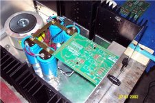
By the way here is a shamless plug of my Aleph. Building mono blocks with 35 volt rails and each mono block should be able to dissipate 200 watts. It won't be long before I will be able to answer my own question.
I have read a number of postings on adjusting R19 to increase or decrease the bias of the current source and I understand that this would contribute to the base current of Q5 and thus the regulation of the current source devices. When R19 becomes so large as to not contribute any base current then all the contribution would be coming from the source resistor voltage which would be a maximum of Vbe or about .66 volts. Now here is the question I have and maybe I'am missing something but wouldnt you have to also increase the bias on the negative driver side also to keep the output offset to a minimum?.
I could see adjusting R19 for fine adjusting of the output offset to compensate for Vgs differences.
By the way here is a shamless plug of my Aleph. Building mono blocks with 35 volt rails and each mono block should be able to dissipate 200 watts. It won't be long before I will be able to answer my own question.
Attachments
Someone correct me if I'm wrong but I think the DC negative feedback to the differential pair will cause the negative driver to be biased higher to compensate for the increased current draw by the current source, as the diff pair attempts to compensate for the DC offset at the output. The actual DC offset of the output may be more affected by the slight mismatch of the hopefully matched differential pair. OW! that hurt.
BPD,
since the current must go somewhere the bias in the positive and negative side will be equal (no load attached). When not Nelson´s bolt of lightning will appear and destroy something very badly
DC offset is not affected by R19 in any way (not counting for effects by running cooler/hotter)
The only thing that could need some adjustment when raising the bias is the current limiter on the negative side. If not the amp will clip on negative inputs.
william
If R19 open does not give enough bias, you can get more
bias by attaching R19 to a voltage divider between the
output and the negative rail and bootstrap the middle
junction to the output through a 220 uF cap. This causes
R19 to draw current out of the junction (Base of NPN
transistor) instead of feeding current in, and so the bias
goes up.
bias by attaching R19 to a voltage divider between the
output and the negative rail and bootstrap the middle
junction to the output through a 220 uF cap. This causes
R19 to draw current out of the junction (Base of NPN
transistor) instead of feeding current in, and so the bias
goes up.
dshortt9
Thank you for the reply. After your reply I realized that the feedback capacitor would keep the DC gain to a minimum ( Rfeedback / Xc) thus the output would try to track the input to the differential pair. If the input was 0 volts then the output would try to follow.
Being a true DIY I think I will experiment and omit the feedback capacitor and install a trimmer at R14, probably a 1k resistor paralled with a2K trimmer pot. This will give me three things. One being complete control of the output driver bias and DC offset. The second removing the capacitor from the balanced signal path. Third give me something to adjust!! Has anyone else gone this route with their Aleph's?
If R19 open does not give enough bias, you can get more
bias by attaching R19 to a voltage divider between the
output and the negative rail and bootstrap the middle
junction to the output through a 220 uF cap. This causes
R19 to draw current out of the junction (Base of NPN
transistor) instead of feeding current in, and so the bias
goes up.
I am sorry to go thread digging but this post from Mr Pass seems very interesting. Has anyone tried it?
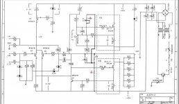
Could Mr Pass himself or another kind soul jot down a schematic of this modification?
Thank you


I hate to ask, but what is max rails for an Aleph 2? Asuumming heatsink to spare, is 70V pushing it?
I have hybrid biamped ESLs (Sanders 10C) and have an itch to build a high voltage A2 amp to try out on the panels.
I have a monster 1.2kv with dual primaries I can series connect to get around 70VDC. I also have a completed A5 and extra output boards, so the some of the work is done...
I have hybrid biamped ESLs (Sanders 10C) and have an itch to build a high voltage A2 amp to try out on the panels.
I have a monster 1.2kv with dual primaries I can series connect to get around 70VDC. I also have a completed A5 and extra output boards, so the some of the work is done...
- Status
- This old topic is closed. If you want to reopen this topic, contact a moderator using the "Report Post" button.
- Home
- Amplifiers
- Pass Labs
- Aleph 2 with 60V rails.