Hi,
I want to build a good quality +/- 15V regulated PSU which I can use for general testing and using with opamps like OPA627, tpa6120 etc.
I purchased this kit:
http://www1.jaycar.co.nz/productView.asp?ID=KC5038
which is very basic, uses a LM320T15 fixed -15V regulator and a LM340T15 fixed +15V regulator and has 1000uF on each rail.
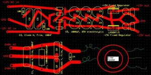
Anyway I want to make it better so I looked at Tangent's STEPS and took some parts of that and just put them straigt on to the Jaycar one.
How does it look? any improvements or mistakes?
Excuse the MS paint bits
I want to build a good quality +/- 15V regulated PSU which I can use for general testing and using with opamps like OPA627, tpa6120 etc.
I purchased this kit:
http://www1.jaycar.co.nz/productView.asp?ID=KC5038
which is very basic, uses a LM320T15 fixed -15V regulator and a LM340T15 fixed +15V regulator and has 1000uF on each rail.
Anyway I want to make it better so I looked at Tangent's STEPS and took some parts of that and just put them straigt on to the Jaycar one.
How does it look? any improvements or mistakes?
Excuse the MS paint bits
Attachments
maxw said:Hi,
I want to build a good quality +/- 15V regulated PSU which I can use for general testing and using with opamps like OPA627, tpa6120 etc.
I purchased this kit:
http://www1.jaycar.co.nz/productView.asp?ID=KC5038
which is very basic, uses a LM320T15 fixed -15V regulator and a LM340T15 fixed +15V regulator and has 1000uF on each rail.
Anyway I want to make it better so I looked at Tangent's STEPS and took some parts of that and just put them straigt on to the Jaycar one.
How does it look? any improvements or mistakes?
Excuse the MS paint bits
Hi I think the kit from Hagtech makes more sense. (part of a phonostage kit)
http://www.hagtech.com/images/powersupply.gif
Re: Re: Help with regulated +/- 15V PSU schematic
thanks, yes that looks good. No mains filter though which is what I liked about the steps.....I dont know what to do now
Elso Kwak said:
Hi I think the kit from Hagtech makes more sense. (part of a phonostage kit)
http://www.hagtech.com/images/powersupply.gif
thanks, yes that looks good. No mains filter though which is what I liked about the steps.....I dont know what to do now
Stephen Soosai said:Three terminal Linear regulator IC such as 7815 and 7915 can't do the job well enough..?
I dont understand. Whats the difference between 7815 and 7915 and the ones in the first schematic? I thought they were more or less identical.
Anyway I have made a pcb design based on the http://www.hagtech.com/images/powersupply.gif image.
Attachments
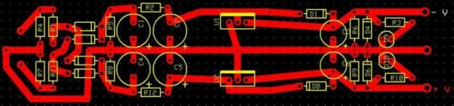
costiss said:if u are intending to design a pcb for this, have the traces much thicker.. especially for the ground, you should build a ground bus ca 1cm thick, so that you dont have any stray- loop currents through your pcb..
OK, thanks!!
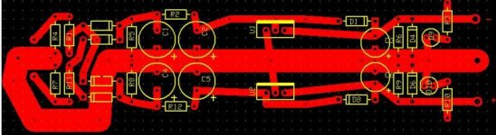
I have redone it with a 6.38 Ground, its the biggest expressPCB will do and if it was bigger it would be tricky to fit under the diodes.
Attachments
moamps said:
Check diodes orientation.
Thank you
I have reversed the ones that are by the regulators.Question: The regulators will supply 1A on each rail, will have to use resisters that are more that 1/4W to draw 1A off of each rail?
Attachments
TL431's cost about $0.25 each and they are a great reference/error amplifier -- much quieter than the 7815/7951 -- the schematic below is gilding the lilly -- you don't need the post regulators (LT17161 LT1964 ultra-low noise -- they are surface mount anyway). This design will cost less and handle more current, the reference is set as Vout = 2.495*(1+R1/R2):
I give credit to Elso for the first part of the design, I modded it for the parts which I have on hand,
An externally hosted image should be here but it was not working when we last tested it.
I give credit to Elso for the first part of the design, I modded it for the parts which I have on hand,
jackinnj said:This design will cost less and handle more current
I am probably wrong but does this mean it will supply 100mA maximum:
"Sink-Current Capability . . . 1 mA to 100 mA"
If so, that is 10x less than the above regulators. I can see that it is a better design but it would cost me more as I would have to order the TL431 from RS components which will cost at least $10 for 2.
I am still not ruling it out though.
What function do the MJE1503x perform? why is it needed so high volts and amps? (150V 8A)?
maxw said:
I am probably wrong but does this mean it will supply 100mA maximum:
"Sink-Current Capability . . . 1 mA to 100 mA"
Those aux transistors do the heavy lifting -- the TL431's supply a reference to the base of the Pass transistors. I use the ones shown in the schematic since I have hundreds of them in stock at my webstore. You can use whatever suits your fancy. The ratio of the two voltage divider resistors differs between the positive and negative supplies.
The LT1761 and LT1964 really aren't necessary unless you need power supply noise in the microvolts -- I just used them in a project from which the schematic is lifted -- they will only handle 100ma or so.
The protocol on DIYAUDIO, one which I respect, is not to flog your stuff, so if you are interested in parts email me privately. I have circuit boards too.
jackinnj said:
Those aux transistors do the heavy lifting -- the TL431's supply a reference to the base of the Pass transistors. I use the ones shown in the schematic since I have hundreds of them in stock at my webstore. You can use whatever suits your fancy. The ratio of the two voltage divider resistors differs between the positive and negative supplies.
The LT1761 and LT1964 really aren't necessary unless you need power supply noise in the microvolts -- I just used them in a project from which the schematic is lifted -- they will only handle 100ma or so.
The protocol on DIYAUDIO, one which I respect, is not to flog your stuff, so if you are interested in parts email me privately. I have circuit boards too.
Thanks jackinnj
I'll have a think about this as I have many options now

I enjoy making my own PCBs and the fact you are all the way in the USA rules out getting any parts from there anyway due to postage costs.
jackinnj said:
Those aux transistors do the heavy lifting -- the TL431's supply a reference to the base of the Pass transistors. I use the ones shown in the schematic since I have hundreds of them in stock at my webstore. You can use whatever suits your fancy. The ratio of the two voltage divider resistors differs between the positive and negative supplies.
Could you use cheap small transisters intsead of the MJE1503x?
eg. BC338 and BC328? if not can you recommend a smaller transister that is more readily available than MJE1503x?
So this design would provide less noise than the design above or an LM317 based PSU?
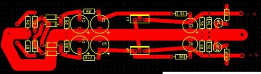
maxw said:I have reversed the ones that are by the regulators.
Look on picture below.
Question: The regulators will supply 1A on each rail, will have to use resisters that are more that 1/4W to draw 1A off of each rail?
Use Ohms law:
P=I x I x R
Regards,
Milan
Attachments
7815
A little off the path sorry but I hopw not too far. Seems like the expertise I need is here.
If I tie a 15 or 16 volt source to the output pin of an umpowered 7815 and 0 to its ground pin will this damage it. I want to be able to jump back an forth between two supplies -- one on board and the other outboard.
Any thoughts thanks
I made a new one with LM317/LM337 as its simple and lower noise the the 79xx regs I had at first:
An externally hosted image should be here but it was not working when we last tested it.
An externally hosted image should be here but it was not working when we last tested it.
lopan said:Looks sweet.
Are D1 and D2 for start up to make sure the output is not more than a diode below the input?
"These diodes protect the regulator when the caps on the OUT and ADJ pins discharge" - quote from http://tangentsoft.net/elec/teps/pguide.html which was one of the schematics I based mine on
To be more precise: If the smoothing caps are small and you for some reason has additional smoothing on the regulated side...and the discharge time is longer in the regulated side than the unregulated, then you need these diodes but normally you don't, espcelly if you have known loads but if you are going to make a general power supply you should have these diodes, just in case. They are for protection purposes only.
- Status
- This old topic is closed. If you want to reopen this topic, contact a moderator using the "Report Post" button.
- Home
- Amplifiers
- Power Supplies
- Help with regulated +/- 15V PSU schematic