Just a quick question.
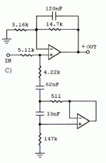
This is basically linkwitz own circuit for dipole compensation. So in other words it EQ's the roll off and removes a peak in the response before roll off. So its a notch filter and a shelving lowpass.
Here is the example of the first circuit
This is basically linkwitz own circuit for dipole compensation. So in other words it EQ's the roll off and removes a peak in the response before roll off. So its a notch filter and a shelving lowpass.
Here is the example of the first circuit
Attachments
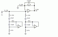
I'm sure one of the Spice Boys can give you a more definitive answer, but it looks to me like you've just paralleled a second GIC. That will drop the frequency corresponding to that input time constant by two, which you could do more simply by changing the capacitors.
To determine whether something will work, the first thing you have to do is say what it is you're trying to do. If you're trying to get a second discrete notch, you'll need a separate buffer/GIC stage.
To determine whether something will work, the first thing you have to do is say what it is you're trying to do. If you're trying to get a second discrete notch, you'll need a separate buffer/GIC stage.
Yes I am trying to add another notch filter, the first for removing the peak in an open baffle and the second the resonance in a W15CY.
Accoding the the linkwitz website the first circuit I posted works just like a notch and lowshelf, and you just use the standard design rules for calculating the notch. I just thought add another notch there save on opamps. But its seems like adding a second notch like I did doesnt add a notch its more works like using components in parallel.
Accoding the the linkwitz website the first circuit I posted works just like a notch and lowshelf, and you just use the standard design rules for calculating the notch. I just thought add another notch there save on opamps. But its seems like adding a second notch like I did doesnt add a notch its more works like using components in parallel.
The notch filter is comprised of the 5.11K resistor and the stuff hanging below it. You'll need another resistor and buffer between notch filters to make it a separate notch filter, if you are looking to damp out two peaks. Notice on SL's site that he says the load must be much greater than the sum of the first two resistors, meaning you cannot daisy chain the notch filters without making the second one very high impedance.
If you are trying to make the notch deeper, just increase the 5.11K resistor. You could also decrease the 4.22K, but that would change the center frequency. I used circuit maker student edition (free) to simulate my notch filter. SL's examples modeled as he predicted, but somehow I wasn't able to use the formulas to get close to my requirements. I modeled in CM and just fooled around with the component values to get the response I was looking for. According to the rightmark analyzer my breadboard notch filter works just about as predicted - imagine that! It also tamed the breakup modes in my woofers nicely.
EDIT: simultaneous posts. Component values I calculated put the center frequency and Q way off - not sure quite why, but I am glad I checked before building the real thing.
By that I assume you are refering to the actual component values chosen. I am wanting to EQ peaks at 300hz and 8200hz.
The one problem with LSPcad is it doesnt let you use your own filters it has stock ones you have to use. I will look at the student version of circuit maker again.
The one problem with LSPcad is it doesnt let you use your own filters it has stock ones you have to use. I will look at the student version of circuit maker again.
Matt,
If you need 100% independency between your two notch filter, I suggest that you place a buffer between them.
I have derived all the formulas needed for making such a circuit (not the shelving bit though)
Do you have access to Mathcad? I can send you some files that might come in handy in you work (and maybe even at school )
)
\Jens
If you need 100% independency between your two notch filter, I suggest that you place a buffer between them.
I have derived all the formulas needed for making such a circuit (not the shelving bit though)
Do you have access to Mathcad? I can send you some files that might come in handy in you work (and maybe even at school
\Jens
I dont know I might be able to get mathcad ive not looked
I have simulated the circuit using Electronics workbench multisim and can see how I can get the circuit to work. However if there is a way to accurately calculate the frequency, Q and by how many dB the notches work to then that would be great.
It seems to me that the first notch filter works well, but the second one requires some additional tweaking to get correct.
Hello,
Yes it will work, but will it do the job you want it to?
I think you will be happier using the gyrator circuit for your EQ sections, as this circuit has some nice features that IMHO make it better for the job.
Also placing a buffer between the two notches will ensure 100% independency between the different circuits.
More information can be found here
\Jens
Jens,
In this particular case there isn't any need for an interim buffer. As mentioned earlier, the circuits are so far different in frequency that there is already 100% independency. In fact, the bass notch filtering circuit option of SL's Phoenix system utilizes four separate gyrators all working in conjunction with a single series resistor. SL has been there and done that a long time ago.
However, I'm wondering why a notch filter would even be required for the 8.2khz peak of the W15. This should be well up into the tweeters range and a typical crossover filter (I am assuming it's 4th-order electrical) by itself should probably attenuate the 8.2khz peak enough not to worry about.
Cheers,
Davey.
- Status
- This old topic is closed. If you want to reopen this topic, contact a moderator using the "Report Post" button.
- Home
- Amplifiers
- Solid State
- Activexover will this work

