>Zen amplifier by BJT?
Some things go well together. Pass-Zen and FET. Some things do not go well together. Pass-Zen and BJT.
The FET has a high input impedance (especially for DC and low audio), and a low but fairly linear transconductance. The BJT has a VERY low input impedance, a lot more transconductance, which varies directly as current.
When you push them hard (as in a Power amplifier), without feedback, FETs (and tubes) tend to 5%-10% THD, transistors over 25% THD and hard to judge because the waveform is so bent that it never really clips on one side, even while flat-lined on the other side.
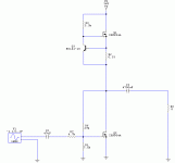
Here's a 15-minute design:
I didn't bother with a literal 1-transistor design: I knew from years of blunt pencils that the input impedance would be impossibly low, and bias would be too sloppy. So I used a Darlington, which is a lot like a single transistor with higher current gain.
Here is a SPICE-simulation run. Never trust SPICE, but it sometimes get the right answer on simple circuits like this. And from my experience, these answers are about right.
The top trace, 2.0V in, is giving 11.3V peak in 8 ohms, or 8 watts (for 178 Watts supply power!). It may not look like it, but distortion is 11% THD: 11% 2nd, 0.65% 3rd, 0.6% 4th, 0.2% 5th, under 0.05% 6th thru 9th.
The bottom trace shows how it will clip horribly, yet stay round on the bottom. Actually the bottom is badly distorted, much weaker than the original. It is more like "the shape of the transistor" (its Gm curve) than the shape of the input.
Also note that the input impedance is a little over 1K ohms, which many folks would call "too low". Not just that it is low, but it varies over the cycle.
Damping is not large, but may be ample for many uses.
Bias stability is poor (though maybe no poorer than the simpler Zens that need a trim-pot).
I made a small attempt to optimize operating point. I expected 8 ohm DC load and 20V collector, but it likes the higher resistor and lower voltage better. It could be a little better, but not a lot.
Much of the distortion could cancel push-pull. But then you have to arrange push-pull drive, still into an annoyingly low input impedance.
And historically: if any 1-transistor plan worked, in days when transistors were expensive, it would have been done. In fact there were 1-transistor megaphones, but they used carbon mikes (VERY high output and DC tolerant), ran DC through their speakers, worked poorly, sounded awful.
Some things go well together. Pass-Zen and FET. Some things do not go well together. Pass-Zen and BJT.
The FET has a high input impedance (especially for DC and low audio), and a low but fairly linear transconductance. The BJT has a VERY low input impedance, a lot more transconductance, which varies directly as current.
When you push them hard (as in a Power amplifier), without feedback, FETs (and tubes) tend to 5%-10% THD, transistors over 25% THD and hard to judge because the waveform is so bent that it never really clips on one side, even while flat-lined on the other side.
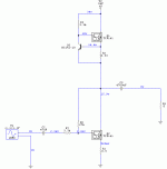
Here's a 15-minute design:
An externally hosted image should be here but it was not working when we last tested it.
I didn't bother with a literal 1-transistor design: I knew from years of blunt pencils that the input impedance would be impossibly low, and bias would be too sloppy. So I used a Darlington, which is a lot like a single transistor with higher current gain.
Here is a SPICE-simulation run. Never trust SPICE, but it sometimes get the right answer on simple circuits like this. And from my experience, these answers are about right.
An externally hosted image should be here but it was not working when we last tested it.
The top trace, 2.0V in, is giving 11.3V peak in 8 ohms, or 8 watts (for 178 Watts supply power!). It may not look like it, but distortion is 11% THD: 11% 2nd, 0.65% 3rd, 0.6% 4th, 0.2% 5th, under 0.05% 6th thru 9th.
The bottom trace shows how it will clip horribly, yet stay round on the bottom. Actually the bottom is badly distorted, much weaker than the original. It is more like "the shape of the transistor" (its Gm curve) than the shape of the input.
Also note that the input impedance is a little over 1K ohms, which many folks would call "too low". Not just that it is low, but it varies over the cycle.
Damping is not large, but may be ample for many uses.
Bias stability is poor (though maybe no poorer than the simpler Zens that need a trim-pot).
I made a small attempt to optimize operating point. I expected 8 ohm DC load and 20V collector, but it likes the higher resistor and lower voltage better. It could be a little better, but not a lot.
Much of the distortion could cancel push-pull. But then you have to arrange push-pull drive, still into an annoyingly low input impedance.
And historically: if any 1-transistor plan worked, in days when transistors were expensive, it would have been done. In fact there were 1-transistor megaphones, but they used carbon mikes (VERY high output and DC tolerant), ran DC through their speakers, worked poorly, sounded awful.
I just realized that the 0.5 Ohm resistor is'nt needed sich the upper transistor determines the Iq.. Allthough it does stabelize Vdc, but this is less critical..
The THD measurements with Spice of the MOSFET evrsion are very accurate, as most of the circuit performance parameters. I don't know if BJT models are as accurate..
Now I could raise the input impedance a little. BTW.. damping factor is higher compared to MOSFET version..
The THD measurements with Spice of the MOSFET evrsion are very accurate, as most of the circuit performance parameters. I don't know if BJT models are as accurate..
Now I could raise the input impedance a little. BTW.. damping factor is higher compared to MOSFET version..
Attachments
 . My work was so busy and busy.
The BJT has a VERY low input impedance
If I don't wrong remind, I thought common collect type has higher input impedance than common emitter. Is it right? Have anyone tried to design Zen amplifier by common collector type?
Hi all
take a look on this thread:
http://www.diyaudio.com/forums/showthread.php?s=&threadid=5270&highlight=
there are some ideas too...
Ciao, Tino
take a look on this thread:
http://www.diyaudio.com/forums/showthread.php?s=&threadid=5270&highlight=
there are some ideas too...
Ciao, Tino
gengcard said:
If I don't wrong remind, I thought common collect type has higher input impedance than common emitter. Is it right? Have anyone tried to design Zen amplifier by common collector type?
I don't think that is typically true because your input resistance goes down as bias current goes up. Since CC amps generally have higher bias than CE amps they will tend to have lower input resistance.
That being said, it isn't necessarily the case for a Zen style amp which has high bias currents to begin with. Since all BJT amps pretty much follow the same small-signal equations, your input resistance will be a function of Hfe, re = 1/gm, and Re = degeneration resistor.
Assuming you have a way around the fact that you don't have any voltage gain in a CC amp and you run either one at the same bias current, then your input resistance differences will depend on Re. With a CC, you'll want Re to be fairly small, with a CE you can get away with a bit more Re which will also help to linearize the behavior.
--
Danny
> I thought common collect type has higher input impedance than common emitter.
Yes, but no voltage gain.
Power amps traditionally take 1V to 2V signals and boost them up to 4V to 40V. Voltage gain is usually 10 or 20. So a CC emitter follower (voltage gain of 1) isn't a complete solution; it requires more complication in an extra voltage-gain stage or a souped-up preamp.
We also need considerable current gain. The input current in a typical power amplifier is less than 0.1mA (1V in 10KΩ); the output current 0.5A to 5A.
So what we really need is a huge Power Gain, around 200,000:1.
The ultimate power gain of a CC emitter follower is essentially Beta. 50+ for a single BJT, 1,000+ for a Darlington. That is not enough, even if you can allow larger input power than most sources can supply.
The ultimate power gain of a CE collector-loaded BJT is Beta times the intrinsic feedback factor, a large number. But in practical cases, especially when delivering power, it is less. Around Beta times load voltage divided by 30mV, or less than 20,000 for a single BJT in an 8W amp.
And if you also want some feedback (and a no-feedback BJT is pretty nasty at high signal levels) then you need 10 or 100 times more power gain to cover the feedback demands. (That's the real difference between CC and CE: the CC has 100% feedback forced upon it, the CE lets the designer choose.)
I'm not hep on FETs; maybe Nelson can jump in. At low frequency, their input impedance is "infinite" and the input power is "zero", so the Power Gain is roughly "infinite". But they have input capacitance which is hard to drive at the top of the audio band. While the capacitance itself does not dissipate power, all ordinary coupling schemes will have power losses when driving capacitance. I think it works out that the naked Power Gain is a little more than a Loudspeaker Amp needs, and when you add feedback it is a little lower than a traditional amp, but tolerable and oh-so-simple.
So a "good" hi-fi loudspeaker amp needs at least two tube stages, a little more than one good FET stage, but at least three and preferably four BJT stages.
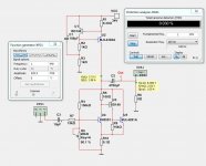
PRR said:> if you take a ZEN
Which of the many-many Zen Variations are you taking?
> and substitue the MOSFET for a TIP141 darlington, you end up with compareble performance specs..
I come up with significantly higher THD and lower input impedance.
Something is wrong here, Rod Elliot has completely different results...
http://sound.westhost.com/project36.htm
It is possible to design a Bipolar ZEN.So a "good" hi-fi loudspeaker amp needs at least two tube stages, a little more than one good FET stage, but at least three and preferably four BJT stages.
Question is why you should do it?
I use tripple darlington in my schematic.
The gain is x7.5.
The THD is less than a normal ZEN amplifier. THD = 0.03% at 1 Watt.
Attachments

Thanks, interesting design, but...I use
Quote from 2004?
THD "should" be lower because BJT transconductance is much higher than any other device.
Why is your R5 so small and your R9 so large? IOW U4 (1st stage) runs rich and U3 (2nd stage) runs lean; normally currents increase stage-by-stage from low-power input to high-power output. (Or is this to damp the radio oscillations of a triple Sziklai?)
- Home
- Amplifiers
- Pass Labs
- Zen Amplifier by Bipolar Junction Transistor