I am interested to built a circuit i notice at http://webook.fset.de/20091999PHCHO/audio/prepre.htm
inside the author recommended to use the transistor recomended to him by toshiba
the transistor is TBC559
is this transistor similar to bc559 made by philips/motorola
i am wondering as tbc559 can't be sourced from where i am staying(M'sia)
any other transistor type that can be used ?
inside the author recommended to use the transistor recomended to him by toshiba
the transistor is TBC559
is this transistor similar to bc559 made by philips/motorola
i am wondering as tbc559 can't be sourced from where i am staying(M'sia)
any other transistor type that can be used ?
An externally hosted image should be here but it was not working when we last tested it.
I think the TBC type are very low noise BC-transistors but not low enough noise for MC pickup. I recommend the SSM2220 (not longer in production but I have those for sale) or the same type in metal can MAT03 from Analog Devices. BCxxx has very different noise specs from different manufactures. Toshiba is the best so far and ON is second. The rest are in third place.
I have just looked into my comparison charts:
The 2SB737R is a low-noise pnp, 50V, 0.3A, 0.25W, 100MHz transistor and a direct equivalent to the BC560 (not the BC559 btw).
This is a pretty basic and ubiquitous transistor here in Europe since many years now. I have good experiences with it in different projects, but be sure to get it from a good manufacturer (as peranders put out already) and source (there are fakes...).
But to get a better performance than using two SSM2220 will be a difficult task, even with careful selection...
Looks a little different from the one in my old l'Audiophile Catalogue
Taken from my catalogue:
<hr width="95%" align=center>
<b>PRE-PREAMPLIFIER
POUR CELLULE A BOBINE MOBILE</b>
<U>VERSION 1</U>
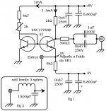
Le jeu de composants de la version 1 est conforme a la description parue dans le n<SUP>o</SUP> 17 de <I>L'Audiophile</I> (figure 1)
Les piles ont ete remplacees par des batteries 6 V 1 AH, qui, outre le fait de resoudre le probleme de la longevity des piles (en moyenne 100 heures), permettent une amelioration subjective tres imnportante (tenue dans le grave, definition, dynamique, recul du bruit, etc.).
Dans certains cas, vu les performances en matiere de bande passante, il est necessaire d'inserer en serie avec l'entree un filtre anti-radio (fig, 2) pour supprimer la reception (captee en generale par les cables platine/pre-preamplificateur).
Le circuit imprime fourni dans le jeu de composants est le meme pour les trois versions, L'implantation des composants est donnee sur la figure 3, Dans ce pre-preamplificateur, il est necessaire d'annuler la derive continue qui apparait a l'entree de la cellule, Pour cela, brancher entre l'entree et la masse un controleur sur l'echelle la plus basse (100 mV) et, a l'aide du trimmer, amener l'aiguille a zero (la cellule ne doit pas etre branchee), La resistance de 3k16<FONT FACE="Symbol">W</FONT> permet d'equilibrer la consommation des parties positives et negatives des batteries.
Dans cette version, I'utilisation des transistors 2SC1775AE ne permet pas d'employer des cellules dont l'impedance de harge est inferieure a 20<FONT FACE="Symbol">W</FONT> (remontee de bruit de fond, chute dans l'aigu, perte de gain), Cette version est donc reservee uniquement a une utilisation avec la DL103 Denon, avec laquelle les resultats sont tout simplement splendides,
<U>VERSION 2</U>
Cette version utilise le meme schema de principe que la version precedente, Toutefois, les transistors utilises sont differents, de meme que le branchement de l'alimentation, Pour une utilisation plus universelle du pre-preamplificateur, nous avons ete amenes a rechercher une autre paire de transistors qui, en matiere de charge de cellule, permet de descendre plus bas,
Le transistor 2SB737R, d'origine japonaise, permet d'obtenir par rapport a l'autre version des caracteristiques de charge (RBB' = 2<FONT FACE="Symbol">W</FONT>) qui rendent ce pre-preamplificateur utilisable avec TOUTES LES CELLULES DU MARCHE dont l'impedance est comprise entre 1<FONT FACE="Symbol">W</FONT> et 40<FONT FACE="Symbol">W</FONT>
De plus, le rapport S/B est ameliore de 6dB, ce qui est enorme, Le haut medium et l'aigu sont encore plus transparents et plus doux,
Le 2SC1775 est un NPN et le 2SB737R un PNP; ces deux transistors ont le meme brochage, Le remplacement sur le circuit imprime oblige a inverser le sens du branchement de l'alimentation par rapport a la version 1: le {+) devient le (-) et le (-) devient le (+), Le trimmer de reglage passe a 3k<FONT FACE="Symbol">W</FONT> et la resistance d'equilibrage de consommation a 6k2<FONT FACE="Symbol">W</FONT>
Ne pas oublier de changer aussi le sens du brancheuent des condensateurs chimiques de 6800uF 10V, Il est bien sur possible d'utiliser les nouveaux transistors dans la version 1,
Cette version utilise des composants a "haute technologie", Dans le domaine de l'audio, nous sommes pour le moment les seuls a vous les proposer:
<LI>condensateurs de decouplage supercapa NEC de 1Farad/5V, dans le volume d'une boite de cachou: 1,000,000uF;
<LI>resistances au tantale.
Les resultats ne se font pas attendre, Avec un tel pre-preamplificateur, il est possible de faire progresser son systeme d'ecoute dans des proportions insoupconnees.
<U>VERSION 3</U>
Ce modele est la version ultime du pre-preamplificateur, Le schema de principe est identique a celui de la version 2.
II emploie aussi, bien evidemraent, des composants a tres "haute technologie" (super capa), mais, ici, toutes les recherches de I'equipe de <I>L'Audiophile</I> en matiere d'alimentation trouvent leur concretisation et leur aboutissement, Cette version pourrait <U>aussi</U> s'appeler <I>pre-preaplificateur Le Monstre</I>, A l'origine, elle a ete realisee uniquement a titre experimental, les resultats hors du commun qu'elle procure nous ont conduits a vous la proposer,
Comme particularites, signalons:
<li> utilisation de batteries au plomb de 8,5A
<li> utilisation de condensateurs de decouplage d'alimentation de 3.4Farad
<li> cablage d'alimentation avec barres de cuivre de 2mm
<li> poids de l'ensemble avec le chassis: 25 kg
Comparee au top niveau de la production mondiale, cette version est toujours sortie victorieuse, Elle permet d'obtenir de vos microsillons un degre de definition, de dynamique, de douceur, de vie, difficilement descriptible par des mots,
Elle constitue pour nous une reference,
<hr width="95%" align=center>
Hope This helps
James
Taken from my catalogue:
<hr width="95%" align=center>
<b>PRE-PREAMPLIFIER
POUR CELLULE A BOBINE MOBILE</b>
<U>VERSION 1</U>
Le jeu de composants de la version 1 est conforme a la description parue dans le n<SUP>o</SUP> 17 de <I>L'Audiophile</I> (figure 1)
Les piles ont ete remplacees par des batteries 6 V 1 AH, qui, outre le fait de resoudre le probleme de la longevity des piles (en moyenne 100 heures), permettent une amelioration subjective tres imnportante (tenue dans le grave, definition, dynamique, recul du bruit, etc.).
Dans certains cas, vu les performances en matiere de bande passante, il est necessaire d'inserer en serie avec l'entree un filtre anti-radio (fig, 2) pour supprimer la reception (captee en generale par les cables platine/pre-preamplificateur).
Le circuit imprime fourni dans le jeu de composants est le meme pour les trois versions, L'implantation des composants est donnee sur la figure 3, Dans ce pre-preamplificateur, il est necessaire d'annuler la derive continue qui apparait a l'entree de la cellule, Pour cela, brancher entre l'entree et la masse un controleur sur l'echelle la plus basse (100 mV) et, a l'aide du trimmer, amener l'aiguille a zero (la cellule ne doit pas etre branchee), La resistance de 3k16<FONT FACE="Symbol">W</FONT> permet d'equilibrer la consommation des parties positives et negatives des batteries.
Dans cette version, I'utilisation des transistors 2SC1775AE ne permet pas d'employer des cellules dont l'impedance de harge est inferieure a 20<FONT FACE="Symbol">W</FONT> (remontee de bruit de fond, chute dans l'aigu, perte de gain), Cette version est donc reservee uniquement a une utilisation avec la DL103 Denon, avec laquelle les resultats sont tout simplement splendides,
<U>VERSION 2</U>
Cette version utilise le meme schema de principe que la version precedente, Toutefois, les transistors utilises sont differents, de meme que le branchement de l'alimentation, Pour une utilisation plus universelle du pre-preamplificateur, nous avons ete amenes a rechercher une autre paire de transistors qui, en matiere de charge de cellule, permet de descendre plus bas,
Le transistor 2SB737R, d'origine japonaise, permet d'obtenir par rapport a l'autre version des caracteristiques de charge (RBB' = 2<FONT FACE="Symbol">W</FONT>) qui rendent ce pre-preamplificateur utilisable avec TOUTES LES CELLULES DU MARCHE dont l'impedance est comprise entre 1<FONT FACE="Symbol">W</FONT> et 40<FONT FACE="Symbol">W</FONT>
De plus, le rapport S/B est ameliore de 6dB, ce qui est enorme, Le haut medium et l'aigu sont encore plus transparents et plus doux,
Le 2SC1775 est un NPN et le 2SB737R un PNP; ces deux transistors ont le meme brochage, Le remplacement sur le circuit imprime oblige a inverser le sens du branchement de l'alimentation par rapport a la version 1: le {+) devient le (-) et le (-) devient le (+), Le trimmer de reglage passe a 3k<FONT FACE="Symbol">W</FONT> et la resistance d'equilibrage de consommation a 6k2<FONT FACE="Symbol">W</FONT>
Ne pas oublier de changer aussi le sens du brancheuent des condensateurs chimiques de 6800uF 10V, Il est bien sur possible d'utiliser les nouveaux transistors dans la version 1,
Cette version utilise des composants a "haute technologie", Dans le domaine de l'audio, nous sommes pour le moment les seuls a vous les proposer:
<LI>condensateurs de decouplage supercapa NEC de 1Farad/5V, dans le volume d'une boite de cachou: 1,000,000uF;
<LI>resistances au tantale.
Les resultats ne se font pas attendre, Avec un tel pre-preamplificateur, il est possible de faire progresser son systeme d'ecoute dans des proportions insoupconnees.
<U>VERSION 3</U>
Ce modele est la version ultime du pre-preamplificateur, Le schema de principe est identique a celui de la version 2.
II emploie aussi, bien evidemraent, des composants a tres "haute technologie" (super capa), mais, ici, toutes les recherches de I'equipe de <I>L'Audiophile</I> en matiere d'alimentation trouvent leur concretisation et leur aboutissement, Cette version pourrait <U>aussi</U> s'appeler <I>pre-preaplificateur Le Monstre</I>, A l'origine, elle a ete realisee uniquement a titre experimental, les resultats hors du commun qu'elle procure nous ont conduits a vous la proposer,
Comme particularites, signalons:
<li> utilisation de batteries au plomb de 8,5A
<li> utilisation de condensateurs de decouplage d'alimentation de 3.4Farad
<li> cablage d'alimentation avec barres de cuivre de 2mm
<li> poids de l'ensemble avec le chassis: 25 kg
Comparee au top niveau de la production mondiale, cette version est toujours sortie victorieuse, Elle permet d'obtenir de vos microsillons un degre de definition, de dynamique, de douceur, de vie, difficilement descriptible par des mots,
Elle constitue pour nous une reference,
<hr width="95%" align=center>
Hope This helps
James
Attachments
ftorres said:Do not try to invert the design. NPNs are usually noisier than PNPs, and noise is the main issue here.
I wouldn't put any money on this statement! NPN and PNP are different by nature (electrons and holes...) but in the datasheets of MAT02 and 03 the noise figures are very much alike.
I have no personal experience in this matter I must add.
NPNs vs PNPs
Just compare page 2 of MAT02 and MAT03 searching for noise voltage density. MAT03 reads better. OK, not by a huge amount, but better.
Once ago, I experienced a diff pair based on these devices, and compared them. Same operating conditions, battery powered, biased by the same current source (CRxxx... don't remember which), and actually, the MAT02 setup was a little more noisy... I stopped here and went with MAT03, but I didn't performed overall tests. Give it a try")
Just compare page 2 of MAT02 and MAT03 searching for noise voltage density. MAT03 reads better. OK, not by a huge amount, but better.
Once ago, I experienced a diff pair based on these devices, and compared them. Same operating conditions, battery powered, biased by the same current source (CRxxx... don't remember which), and actually, the MAT02 setup was a little more noisy... I stopped here and went with MAT03, but I didn't performed overall tests. Give it a try
Common Base Head Amplifiers
Nelson,
Marshall Leach designed a common base headamp and published in Audio Magazine years ago.
http://users.ece.gatech.edu/~mleach/headamp/
PS Audio also used a common base headamp in their preamp, this also going back a few years. (In their case they converted the first transistor of the differential in the phono stage to a common base amp).
Jam
Attachments
The original question was alternate transistors for the Hiraga MC.
I did quite a lot of transtor swapping in the early 90´s. It turned out that the C1775, A872, C2389 and B737 all gave too much "bite" to the music. Initially a sense of dynamics is perceived, but after some hours of listening it was not deemed neutral. These transistors put too much focus on the high frequency range.
The BC´s I tried sounded just plain bad, distorting badly compared to the japanese transistors.
I stumbled across the A1038 from Rohm. That made a big difference. A beautiful midrange without the excess high frequency fuzz of the others. Far better than the Hiraga original. Highly recommended.
Eqvivalents are A1579(smd) and A1514(smd).
Regards
Syl
<a href="http://www.hilberink.nl/amps/amps.htm">www.hilberink.nl/amps/amps.htm</a> show the schematic I posted earlier
and and has this:
<font color=#800040><i>Below a evaluation of the original design of Hiraga of 1988. This design has all the advantages of a modern well riped design but lacks some limitations of the basic Hiraga design. As far as I know this design was never published in this form, a very similar design was published in Elektor. </i></font>
<a href="http://www.hilberink.nl/amps/amps7.htm"><img src="http://www.hilberink.nl/amps/hiraga4.jpg" ></a>
<font size="-2">pic a link</font>
James
My Hiraga MC preamplifier
Hi,
Firstly i built a very successful MM preamp. I modified the Audionote M7-M10 schematics. Now, it use 4*6072+2*6N30P-DR. Sounding incredible natural, sweet and detailed. Then i decided to built a Hiraga MC pre with 8 pins IC sockets on main board. I prepared (soldered) 2SA1038 and BC560 transistor pairs on seperate 8 pins sockets. Now, i can easily insert any of them in the sockets located on the board and compare the sound. Before this off course i am making adjustments with trimpots to ensure ''0'' Volt at the enter of the preamp. I can say that; this preamp and DENON 103R is sounding excellent with both transistors. But, my favorite is 2SA1038 -Thanks syl- I used 500.000uf capaciy for each channel. Electrolytic caps are 6800uf Elna Cerafine, cables are teflon coated silver. I will install a power switch and a socket for charging the batteries.
Noyan
Hi,
Firstly i built a very successful MM preamp. I modified the Audionote M7-M10 schematics. Now, it use 4*6072+2*6N30P-DR. Sounding incredible natural, sweet and detailed. Then i decided to built a Hiraga MC pre with 8 pins IC sockets on main board. I prepared (soldered) 2SA1038 and BC560 transistor pairs on seperate 8 pins sockets. Now, i can easily insert any of them in the sockets located on the board and compare the sound. Before this off course i am making adjustments with trimpots to ensure ''0'' Volt at the enter of the preamp. I can say that; this preamp and DENON 103R is sounding excellent with both transistors. But, my favorite is 2SA1038
-Thanks syl- I used 500.000uf capaciy for each channel. Electrolytic caps are 6800uf Elna Cerafine, cables are teflon coated silver. I will install a power switch and a socket for charging the batteries. Noyan
An externally hosted image should be here but it was not working when we last tested it.
An externally hosted image should be here but it was not working when we last tested it.
An externally hosted image should be here but it was not working when we last tested it.
An externally hosted image should be here but it was not working when we last tested it.
An externally hosted image should be here but it was not working when we last tested it.
Last edited:
Hiraga MC etc
Hi!
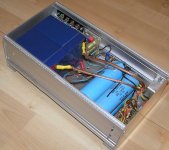
I build this Hiraga MC amp many years ago. Not very elegant, but it worked quite well.
I guess it still does, except that the accumulators are probably dead by now.
With the power switch in ON position, the mains is OFF.
In OFF postition, the mains is ON, causing the accumulators to trickle-charge.
The project was from a reprint in a Swedish magazine in the '80s.
Schematic, box and PCB
Hi!
I build this Hiraga MC amp many years ago. Not very elegant, but it worked quite well.
I guess it still does, except that the accumulators are probably dead by now.
With the power switch in ON position, the mains is OFF.
In OFF postition, the mains is ON, causing the accumulators to trickle-charge.
The project was from a reprint in a Swedish magazine in the '80s.
Schematic, box and PCB
Attachments
The "etc"
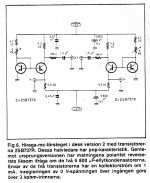
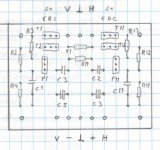
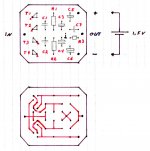
My second MC amp was from WW, also in the 80's. Looks like a Leach clone, or cloned by him, I don't know.
Anyway, it works really well and I used it for a few years.
Schematic, board layout and specs
My second MC amp was from WW, also in the 80's. Looks like a Leach clone, or cloned by him, I don't know.
Anyway, it works really well and I used it for a few years.
Schematic, board layout and specs
Attachments
- Status
- This old topic is closed. If you want to reopen this topic, contact a moderator using the "Report Post" button.
- Home
- Source & Line
- Analogue Source
- Jean Hiraga Mc circuit