Hello all... village idiot here.
I was looking for a low-cost, high performance amp for my system and came across the Gain Clone. With all the positive feedback I read I felt I couldn't pass it up.
So, I ordered the boards from Brian Bell (BrianGT) and gave myself a weekend project. Fast forward to the finished product, and I've found I have an issue with some unwanted intermittent distortion bleeding into the output signal... a steady "pulse," almost if there was a switch being turned on and off.
I thought it may be a grounding issue, so I went back and checked everything out and it seems to be correct. Another thought is that I may have incorrectly wired one of the xformer leads. Perhaps it's something that your experienced eye could spot immediately. Me, on the other hand, have very little electronic engineering experience and I'm learning as I go along (if that wasn’t obvious).
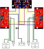
I've attached a couple of diagrams outlining exactly how the amp is wired. One is a PS schematic (in this post) and the other is the GC board schematic (in the following post). I’m hoping that it’s an obvious and easy fix. BTW, I used an AVEL Y236750 330VA 25V+25V TT.
Any help is greatly appreciated!!!!
Cheers,
Hat
I was looking for a low-cost, high performance amp for my system and came across the Gain Clone. With all the positive feedback I read I felt I couldn't pass it up.
So, I ordered the boards from Brian Bell (BrianGT) and gave myself a weekend project. Fast forward to the finished product, and I've found I have an issue with some unwanted intermittent distortion bleeding into the output signal... a steady "pulse," almost if there was a switch being turned on and off.
I thought it may be a grounding issue, so I went back and checked everything out and it seems to be correct. Another thought is that I may have incorrectly wired one of the xformer leads. Perhaps it's something that your experienced eye could spot immediately. Me, on the other hand, have very little electronic engineering experience and I'm learning as I go along (if that wasn’t obvious).
I've attached a couple of diagrams outlining exactly how the amp is wired. One is a PS schematic (in this post) and the other is the GC board schematic (in the following post). I’m hoping that it’s an obvious and easy fix. BTW, I used an AVEL Y236750 330VA 25V+25V TT.
Any help is greatly appreciated!!!!
Cheers,
Hat
Attachments
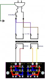
it loks like the output from PS out is wrong I have older PS pcb but on mine the outputs are grouped as V- first 2 and second 2 are power + (this is for -ve supply) thiss is marked PG-.
the next set of 2 is PG+ but this is really the -ve of the plus power supply lastly the V+ is the positive of =ve supply
these 2 supplies are seperated until the amp board
look at the small cap each side has 2 connectors
Each amp board going from left to right V+ as the first and second PG+ these match exactly to PS board
I may go to Texas just for saying this (it has happened before), but here it goes:
Try the amp without earth, disconnect the cable from the plug.
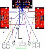
Anyway, it's better to use it with a 0.1uf cap parallel with a 100R resistor, not directly to star ground as you have.
And you should rearrange those grounds, as moamps says.
Try the amp without earth, disconnect the cable from the plug.
Anyway, it's better to use it with a 0.1uf cap parallel with a 100R resistor, not directly to star ground as you have.
And you should rearrange those grounds, as moamps says.
I wanted to thank all of you for your replys. Unfortunately, after taking the suggestions and trying them, and variations of them, on my gc, i've found that i'm still plagued by this distortion problem.
i've gone as far as replacing the amp chips and still, nothing.
i'm considering starting the boards from scratch again and see if i have the same problem.
if anyone has any other suggestions before i begin again, it'd be greatly appreciated.
best,
hat
i've gone as far as replacing the amp chips and still, nothing.
i'm considering starting the boards from scratch again and see if i have the same problem.
if anyone has any other suggestions before i begin again, it'd be greatly appreciated.
best,
hat
actually, they are. but i've mounted the chips to a 7" x 1.5" x .5" heatsink (it runs along the length of the chassis. i used artic silver when mounting them as well. i would think they would be pretty well protected, but i could be wrong...
Just checking - are you using insulated chips or are you insulating the non-insulated versions from the heatsink?
hatfield said:I'm using the insulated version (LM3875TF)
Touch up all the solder joints with a hot iron.
With the TF version and +/- 25 VDC you need a heat sink with ~6 C/W rating. You may be getting some thermal cutoff (but before rushing out to get a bigger heat sink check your grounds, solder joints etc.) I don't really think that it is a heat sink problem since there is a bit of hysterisis between the sink itself heating up (i.e. the heat sink is warm and keeps the part warm for a fraction of a second after the thermal cutoff) then cooling down -- it doesn't happen in tens of microseconds !
Make sure your electrolytics are installed correctly too.
GC intermitent noise
Not solved the issue yet?
If not, a couple of questions:
Does the noise appear in both amplifiers?
If so, does it happen synchronously (both at the same time)?
Does it apear from the onset or does it take some time to develope?
Is it output power related? (i.e. changes with listening level?)
Do you have the possibility of getting an osciloscope, some friend who owns one and can help?
Let me know and I will provide further directions to diagnose and solve the problem.
Rodolfo
- Status
- This old topic is closed. If you want to reopen this topic, contact a moderator using the "Report Post" button.
- Home
- Amplifiers
- Chip Amps
- CG Distortion Issue