I have seen the threads on the I/V converter but that is not what i need !
1st off all, when is a circuit an V/I Converter ?
When it has a sufficient low output resistance and is able to deliver enough current (class-A) ?
Using Current is a nice way to transport information over.
And since i am thinking of a modular pre-amp (multiple preamp boards on a motherboard like accuphase is doing) i am thinking of their idea on V/I conversion !
Any one suggestions / idea's ?
grtz
Simon
If you are thinking about building it yourself using transistors and not op-amps, then you could look at those pre-amplifier DIY projects, you can find on the net, and then take away everything after the VAS-stage, including the bias-regulating circuit. The VAS-stage normally gives out current. But then you need to look at the other end: The input stage of the "reciever". You will have to match the output current with the impedance of the input stage.
blu_line said:[snip]1st off all, when is a circuit an V/I Converter ?
When it has a sufficient low output resistance and is able to deliver enough current (class-A) ?
[snip]
Hi Simon,
The output impedance of a V/I converter is ideally infinite. That means, it will deliver an output current controlled by the input voltage. The output voltage then depends on the load. V/I converters are a nice way to control a stage gain without feedback.
BTW, you may think that if you load a V/I stage by an infinite load, that would give infinite output voltage and thus infinite gain! Not so, because the max output voltage depends also on the supply voltage of the circuit, of course. Normally the max voltage that the output can give, while still maintaining the output current is called the compliance. MAX435/436 are examples of V/I converters.
Jan Didden
MAX435/436 are examples of V/I converters
Checked those out !
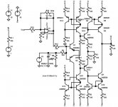
What kind of performance could be expected when build up by discretes ?
Got something in my LT Spice but that isn't promissing !
Attachments
S-T,
What you need are a couple of THAT340's or others of the family, from www.profusionplc.com (BTW, I'm going to order a couple, you want to join?).
Jan Didden
What you need are a couple of THAT340's or others of the family, from www.profusionplc.com (BTW, I'm going to order a couple, you want to join?).
Jan Didden
Hi Simon,
Any differential pair is actually a voltage to balanced current converter. The only problem is that the input voltage range is very limited without emitter or source degeneration. The link gives an overview of several techniques to increase the input voltage range and the linearity of voltage to current converters.
http://www.eecg.toronto.edu/~kphang/ece1371/mixers.pdf
Steven
Hi Simon!
I feel that a fully discrete solution is difficult, if you want
good performance.
If you have issues to get such kingly components from Burr Brown etc.,
then you could try the old LM13600 (NATIONAL and probably lot's of remakes).
Please refer to:
http://www.national.com/pf/LM/LM13600.html
It is a dual transconductance amp, easy to get, low cost.
Performance is OK for "Lo-Fi" and most other analog signal conditioning. If you only need one transconductance amp, then you can parallel both internal amp of the LM13600. This will give you 3db better S/N ratio.
Cheers
Markus
yeah, i had a look at the lm13600.
Performance is awful.
I realy need a hi-fi type.
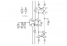
The goal is to see whether audio can better be transported via an normal buffer (Vin/Vout) or transconductance amp (Vin/Iout).
I did some simulations on 2 types of circuits. topology is quite the same , and so are the result (disappointing).
Circuit is realy working perfect, but the 2nd and 3rd harmonic are a disaster.
grtz
Simon
Performance is awful.
I realy need a hi-fi type.
The goal is to see whether audio can better be transported via an normal buffer (Vin/Vout) or transconductance amp (Vin/Iout).
I did some simulations on 2 types of circuits. topology is quite the same , and so are the result (disappointing).
Circuit is realy working perfect, but the 2nd and 3rd harmonic are a disaster.
grtz
Simon
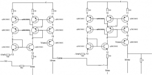
If it is for current signal transport between devices i have seen a discrete version in a Swedish hifi magazine (High Fidelity) many years ago.
It included a "transmitter" and "receiver" which was in fact a V/I and I/V converter respectively.
Cannot remember if i have the article still, will check but i promise nothing.
In fact if you take the Yadis in the digital thread and terminate the input voltage via a series resistance. Remove the parallel output resistance. Take the output to another yadis input stage with normal configuration you would have a working setup.
This is just to show an example.
What happens if you use a high quality nmos transistor on the output as an emitter follower and a current sink. The other end is terminated in a opamp based IV stage?
If this is not what you are looking for then i am sorry.
Attachments
Hi All,
Aha! It's a interesting work. In the industry applications, current transmittal are very common used in high noise environment. One of the most notable benefit is high noise tolerance thanks to very low(near to zero) input impedance.
In audio applications, as my understand the advantage of current transmittal will be low sensitivity to interconnect cable! If input impedance of receiver is low enough and output impedance of transmitter is high enough, then the impedance of interconnect cable which paralleled on receiver's input port can be ignore (at least in audio band is not too hard to achieve )! In the other words interconnect cable will not effect sonic preformance! So, why we need to pay for high price interconnect cable?! (Now, I thing that guys from high price cable manufactory and agent wanna kill me
 and reject my thought!
 ) Isn't it?
I'm now working on a pair of modulars for this thought......
Any suggestion?
Wenyeh
Aha! It's a interesting work. In the industry applications, current transmittal are very common used in high noise environment. One of the most notable benefit is high noise tolerance thanks to very low(near to zero) input impedance.
In audio applications, as my understand the advantage of current transmittal will be low sensitivity to interconnect cable! If input impedance of receiver is low enough and output impedance of transmitter is high enough, then the impedance of interconnect cable which paralleled on receiver's input port can be ignore (at least in audio band is not too hard to achieve )! In the other words interconnect cable will not effect sonic preformance! So, why we need to pay for high price interconnect cable?!
(Now, I thing that guys from high price cable manufactory and agent wanna kill me and reject my thought! ) Isn't it?I'm now working on a pair of modulars for this thought......
Any suggestion?
Wenyeh
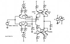
I've seen transcoductance amp, current conveyors and etc etc on my search for the VI converter.
The current conveyor is most promissing i think !
Unfortunatly i can not get the bias right. Any one ?
Most worrying to me is what to do with the input where R6 is connected to !
grtz
Simon
The current conveyor is most promissing i think !
Unfortunatly i can not get the bias right. Any one ?
Most worrying to me is what to do with the input where R6 is connected to !
grtz
Simon
Attachments
Hi Simon-Thijs,
If this current conveyor is your transmitter, then leave out R5 to get a nice current source output with high impedance and good voltage compliancy. R6 is the voltage to current conversion resistor and should be connected to ground (as shown). This will give you a bipolar single-ended voltage input to bipolar single ended current output. With R6 is 1k (as shown) 1V rms in gives you 1mA rms out.
For the receiver you can use the same circuit but use the other input. That means making R3 zero and applying the signal current, coming from the transmitter, to the emitters of Q11 and Q12. Leave out R6. R5 is the conversion resistor from current to voltage. If R5 is 1k, then the output voltage will be 1V rms again.
Steven
Simon,
Your post was a very common topology of current mode op called CCII. It's a class AB design with high bandwidth and low noise. But, the problem is low CMRR and low PSRR of this kind of circuit. And, it contain potential unstabilization in high frequency in this circuit due to standard wilson-CC emploied.
In the other hand, this CCII circuit contain potential accurate degrade by input stage.
For more infomation you can read many relate article of current mode technoloy...")
Your post was a very common topology of current mode op called CCII. It's a class AB design with high bandwidth and low noise. But, the problem is low CMRR and low PSRR of this kind of circuit. And, it contain potential unstabilization in high frequency in this circuit due to standard wilson-CC emploied.
In the other hand, this CCII circuit contain potential accurate degrade by input stage.
For more infomation you can read many relate article of current mode technoloy...
Thanks Steven , i keep being amazed by your knowledge !
Found some nice documents of the CCI and CCII on the net.
I managed to set the DC output voltage to 0 via an intergrator.
To bad. Its equivalent circuit wherein the Q1 and Q2 are switched (see Per Andersons diamond buffer) the DC offset was 0.
Thanks Wenye.
But please explain what you mean with :
Another problems popped up.
Did anyone ever do a FFT of an LT-Spice Sinus Source ?
I hoped they where clean, but they show 2nd and 3rd harmonics.
best regards,
Simon
Found some nice documents of the CCI and CCII on the net.
I managed to set the DC output voltage to 0 via an intergrator.
To bad. Its equivalent circuit wherein the Q1 and Q2 are switched (see Per Andersons diamond buffer) the DC offset was 0.
Thanks Wenye.
But please explain what you mean with :
In the other hand, this CCII circuit contain potential accurate degrade by input stage
Another problems popped up.
Did anyone ever do a FFT of an LT-Spice Sinus Source ?
I hoped they where clean, but they show 2nd and 3rd harmonics.
best regards,
Simon
- Status
- This old topic is closed. If you want to reopen this topic, contact a moderator using the "Report Post" button.
- Home
- Amplifiers
- Solid State
- V/I Converter