As the title states, looking to build my first IC based amplifier. Most likely a LM3886 from a reputable dealer, good (but not bankrupting) components, mounted on a PCB and nice enclosure. The enclosure is the only aspect I'm not sweating. As of right now, this is the wishlist:
-2 RCA input channels, mainly one for phone and one for TV
-Separate power supply (I like how it looks aesthetically) with XLR between PS and Amp
-Design the PCB to keep the signal as short as humanly possible (duh) with Thiele and Zobel networks
-ALPS Blue Velvet pot with room to expand to the motorized version in the future or stepped attenuator
-The whole build based on the KISS principle; keep it simple, stupid
Now onto my main questions:
-How would one go about gauging input impedance when using two assumingly different inputs like a phone and TV to generate enough output power that I won't constantly have to adjust volume? Also, does it particularly matter if one input (i.e. TV) will be the main input? Could I simply plug in a stereo headphone jack and use a multimeter to take measurements off the other end?
-Is point to point going to be far superior to a PCB in regards to simplicity and function? I like this, but it seems daunting with my current soldering skills: Micro-Amp › Circuit Design
-What is the best way to terminate wires into a PCB? I have seem many phoenix type being used, but how does this compare to being soldered directly to the board? Circuit Basics uses crimped type connectors to connect everything. Does any of this have an effect on signal?
Most everything else I think I have a pretty good grasp on. Not new to soldering or electronics but definitely new to building amplifiers. I can do the math to calculate values for components, which has been a lot of my research but the questions asked I have searched and searched with no real conclusive answers. Most likely overthinking on my part. Cheers guys, and sorry if these are complete noob questions.
....How would one go about gauging input impedance when using two assumingly different inputs like a phone and TV to generate enough output power that I won't constantly have to adjust volume?....
There is no magic answer.
Impedance is not the issue. Your power amp input will be much higher impedance than typical sources. You will get 98+% of the voltage out of the source.
But there is no reason to expect a cellfone and a TV to output the same voltage. The TV may be generic DAC 2.0V, or may be some lesser figure. Cellfones are mostly headphone drivers and with 32 phones the output may be nearer 0.2V; anyway the usual 3V cell battery does not allow 2V levels any simple way.
The super-simple trick is to mark your volume control with nominal settings for TV and Cell. TV may like "3" (on 0-10 scale) while Cell may demand "9". Of course your actual setting depends on the music and the time of day. But this helps you not to go "OWW!!" when you switch sources.
The other way is a source switch, including a pad for the louder source. Say you scale for the 0.2V assumed from Cell. Two other TV jacks go through 10:1 pads to the Cell/TV switch. (This also avoids re-patching.)
Problem: the usual chipamps are scaled for sources near 0.7V. The Cell may even want a booster. Alternatively you can pick resistors around the power amp for higher gain.
A lot of these decisions do not properly fall on a Power Amp but are usually relegated to a Line Amp. Jacks, maybe per-source pads, source switch, volume control, a little spare gain. This of course can be built in with the power amp and tap its power.
Point to pointing is like knitting you can listen to. It is fun when it works first time but it's a nightmare to replace a part if it doesn't.
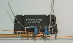
Never rely on the solder for mechanical strength, twist things together before soldering. For a first point to point you could try an LM1875, only 5 legs to deal with and a relatively cheap power supply cost.
Never rely on the solder for mechanical strength, twist things together before soldering. For a first point to point you could try an LM1875, only 5 legs to deal with and a relatively cheap power supply cost.
First Chip Amp Build - Need Insight....
-Is point to point going to be .... I like this, but it seems daunting with my current soldering skills: Micro-Amp › Circuit Design....
Oh, golly. I've done dead-bug and other "knitting" techniques, but that guy takes it way further than I care to even look at.
"First Chip Amp Build" -- buy a PCB off eBay. There's no objective problem with this technique, it is used in some very fancy gear, and the asians will sell a sometimes-excellent PCB for postage.
Attachments
P2P can be done with good results but there is no reason why it should be superior to a decent PCB. On the other hand, the pcb has some strong advantages, especially wrt reliability and ease of soldering.
If you're worried and really want the best pcb for a simple lm3886, there's always the lm3886 done right. It's a bit pricey at 39$ a board but you'll get good support from Tom for a first built.
side note: I think we really should have an open source pcb for the lm3886 on osh park...
If you're worried and really want the best pcb for a simple lm3886, there's always the lm3886 done right. It's a bit pricey at 39$ a board but you'll get good support from Tom for a first built.
side note: I think we really should have an open source pcb for the lm3886 on osh park...
There is no magic answer.
Impedance is not the issue. Your power amp input will be much higher impedance than typical sources. You will get 98+% of the voltage out of the source...
The super-simple trick is to mark your volume control with nominal settings for TV and Cell. TV may like "3" (on 0-10 scale) while Cell may demand "9"...
The other way is a source switch, including a pad for the louder source. Say you scale for the 0.2V assumed from Cell. Two other TV jacks go through 10:1 pads to the Cell/TV switch. (This also avoids re-patching.)
Problem: the usual chipamps are scaled for sources near 0.7V. The Cell may even want a booster. Alternatively you can pick resistors around the power amp for higher gain...
That makes sense, I always though a normal cellphone had a little higher voltage though. Is a pad like a DIM switch? I was already planning on setting the gain slightly higher originally for running only a single input.
Also, would a passive preamp help to choke the TV input to where it would be more ideal?
Never rely on the solder for mechanical strength, twist things together before soldering. For a first point to point you could try an LM1875, only 5 legs to deal with and a relatively cheap power supply cost.
I toyed with the idea of doing that same thing but with a TDA2050
If you're worried and really want the best pcb for a simple lm3886, there's always the lm3886 done right. It's a bit pricey at 39$ a board but you'll get good support from Tom for a first built.
side note: I think we really should have an open source pcb for the lm3886 on osh park...
I hadn't seen that board before, but might throw it into consideration. I was going to use EasyEDA and go through them for the PCB. I've read good things about them and the price isn't too bad either. Basically design the board around a few layouts I've seen and what my own needs may be. Sames with the board for the PS and maybe even for the Thiele networks, and using it as a "proof of concept" for my first project.
If you intend to draw your own board, a few threads are useful reading:
- LM3886 PCB vs Point-to-Point (with data)
- LM3886 Layout ok? (starting at post 74)
- LM3886 layout and some questions
Plus the pages on the lm3886 on Tomchr's website.
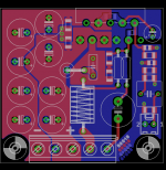
I'm waiting for a small (less than 5*5cm) pcb for the lm3886 to come from the pcb fab in China. I'll let you know how it turns out.
- LM3886 PCB vs Point-to-Point (with data)
- LM3886 Layout ok? (starting at post 74)
- LM3886 layout and some questions
Plus the pages on the lm3886 on Tomchr's website.
I'm waiting for a small (less than 5*5cm) pcb for the lm3886 to come from the pcb fab in China. I'll let you know how it turns out.
Attachments
apex gainclone ,
LM3886 Schematics + PCB
Contact Prasi(http://www.diyaudio.com/forums/members/prasi.html) for more info.
LM3886 Schematics + PCB
Contact Prasi(http://www.diyaudio.com/forums/members/prasi.html) for more info.
If you intend to draw your own board, a few threads are useful reading:
- LM3886 PCB vs Point-to-Point (with data)
- LM3886 Layout ok? (starting at post 74)
- LM3886 layout and some questions
Plus the pages on the lm3886 on Tomchr's website.
I'm waiting for a small (less than 5*5cm) pcb for the lm3886 to come from the pcb fab in China. I'll let you know how it turns out.
I really like how Tomchr lays out his writings. For a visual learner like me it's tough to just read an article with nothing practical in front of me. Thanks for the links!
- Status
- This old topic is closed. If you want to reopen this topic, contact a moderator using the "Report Post" button.
- Home
- Amplifiers
- Chip Amps
- First Chip Amp Build - Need Insight