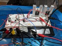
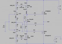
Since I am going in a different direction than the other F4 beast builders, and I don't want to pollute what L H Quam is doing with the bias analysis, here is the front end of my "Beast with hundreds of amperes". I will journal the project in this thread.
The inputs are matched K170/J74 from Punkydawgs.
Rail voltages are +/- 24V.
There are 200 ohm pots in the drains of the input Jfets. Idss of the Jfets is about 8 mA.
The LATFETS require about 0.495v bias each for 50mA of current with the LATFETS at operating temperature. Cold, the bias voltage needed is 0.693v each. The Vgs of the LATFETS are identical at 50mA.
This initial plug-in arrangement is to learn how to set the bias voltages for proper operation.
There are some solder perfboard proto boards on order to make this mountable to the massive heat sink that holds the pucks.
There is a 1-ohm resistor between the LATFET drains to monitor current. The bias spreader for the pucks will go here in the final build.
Attachments
Last edited:
Here are some observations and measurements and changes made.
I was biasing both LATFETS at around 0.495v.
The first observation was that the K1058 was getting much hotter than the J162. Measuring voltages, almost all of the 48v of combined power supplies voltage was across the K1058.
I pulled the LATFETs and ran the Vgs test again. I tied the drain to gate and then forced 50mA through the device. Both LATFETs measured 0.693 Vgs with 50mA forced through them.
Next I performed a curve trace test biasing the D-S at 20V and then adjusting the G-S voltage for 50mA of D-S current.
The J162 requires -0.27V Vgs for -50mA at -20V and the K1058 requires 0.62V Vgs for 50mA at 20V.
Armed with that info, I adjusted the 200 ohm pots for -0.27v Vgs on the J162 and 0.62V on the K1058. This causes very close to 50 mA to flow and the K1058 is no longer hogging all of the 48v.
I was able to make a fine adjustment to the 0.62V bias pot to balance the voltages across the LATFETs.
My assumption is that the Vgs test does not bias the D-S channel into the region where it will be used. You have to test the device at the D-S voltage where it will be working to know what bias voltage to use.
Comments?
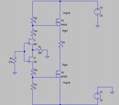
Just a small point but M1 and J2 should be flipped vertically if you wish to follow normal convention and/or wish to simulate the circuit. I appreciate that you have made the drain and source connection explicit for M1/M2 but it is usually easier and less confusing to follow convention...
Just a small point but M1 and J2 should be flipped vertically if you wish to follow normal convention and/or wish to simulate the circuit. I appreciate that you have made the drain and source connection explicit for M1/M2 but it is usually easier and less confusing to follow convention...
Thank you for pointing out the mistakes. This version should be correct.
Attachments
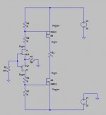
That looks better")
Thank you for reviewing and correcting.
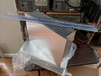
Heat Sinks have arrived
I bought three heatsinks from USA Heatsinks dot com. These are 10.08" long. I ordered three of them 7" tall. The picture is with a 15" ruler on top for perspective.
The only downside I notice so far is that where they are cut is a burr edge. It will require some time to remove all of the burr edges.
The weight of the 10.08" x 7" sink is 6 lbs 12 oz. (3.06 kg).
Some solder proto strip boards will arrive Monday. Then commences soldering up a driver board with K170/J74 inputs and K1058/J162 outputs with an FQP3N30 for a bias spreader.
Attachments
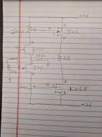
Most of the parts are here. Did some verifying of voltages and currents of the first two stages and placed those on the drawing.
The input stage idles at 8mA.
The LATFETS idling at 50mA require 0.26V Vgs for the J162 and 0.6V Vgs for the K1058. It would be nice to have matching LATFETs.
No capacitors anywhere.
My guess is that an NTC thermistor will be needed on the heatsink and included in the bias spreader for thermal OPS bias stability.
Attachments
Since I am going in a different direction than the other F4 beast builders, and I don't want to pollute what L H Quam is doing with the bias analysis, here is the front end of my "Beast with hundreds of amperes".
What are you doing differently? For people that haven't followed the Beast thread?
What are you doing differently? For people that haven't followed the Beast thread?
1. I am not using a cascode input state
2. I am using LATFET in the driver stage
3. They are using much higher voltage which makes sense if you want to drive an 8-ohm speaker
4. They are implementing a servo bias much the same as the PL amplifier
5. I am going for super high current output at much lower voltage into very low impedance loads.
One of the intended applications is to drive a low impedance ribbon directly with almost unlimited current.
I just checked the other thread.
Your design follows better my needs
I like to think of of what I am attempting as an F7 driving a lower impedance XA25 OPS without the current sensing nor current limiting nor safety shutdown etc etc.
I appreciate your interest. It will be running fairly soon.
- Status
- This old topic is closed. If you want to reopen this topic, contact a moderator using the "Report Post" button.
- Home
- Amplifiers
- Pass Labs
- F4 Beast with hundreds of amperes