That's too broad a question without knowing what the problem is or how you perceive it and whether you have some basic repair skills and equipment - at least a multimeter, anyway. For some indication of what may be involved, there are several A240 repair threads here already, which you can search with Google etc. or use our own search engine, if you like challenges.
Hint: There's no service manual or schematic available for download that I'm aware of and that makes communication very difficult, since we can't identify what to do or where, inside the case. A few members have supplied a manual by PM in the past, perhaps someone might post it here or at least forward it to interested parties again, as we all like to know what threads are about.
Hint: There's no service manual or schematic available for download that I'm aware of and that makes communication very difficult, since we can't identify what to do or where, inside the case. A few members have supplied a manual by PM in the past, perhaps someone might post it here or at least forward it to interested parties again, as we all like to know what threads are about.
Last edited:
I have a multi meter and I printed the schematic from vinyl engine. I have no training so i only understand basics. the amp recently blew one channel's output devices and drivers.after replacing them the fuse still blows on power up. I then disconnected the transformer output going to pin 1. The fuse didn't blow but the bridge rectifier started smoking. not sure if it was already short before and that kept causing the fuse to blow or I had killed it by disconnecting pin 1.
If I'm looking at the correct circuit (hand scrawled), then it should be fairly straightforward to fix.
You must use a bulb tester for faultfinding. It saves burn ups and major blowing of semiconductors.
If the bridge is smoking then it must replaced irrespective of whether it has survived or not.
You can then fault find in the normal way (bulb tester in use) and see what is going on.
I can't just see the power supply in the manual I am looking at but it will be a basic text book design and easy to troubleshoot.
Thanks, Tomorrow I will get a new RS403L.
If the bridge was short before I overheated it, that was what kept blowing the fuse. Could the bridge have gone short because the output transistors of one channel failed?
Can you please show me a link with instructions how to make a bulb tester.
If the bridge was short before I overheated it, that was what kept blowing the fuse. Could the bridge have gone short because the output transistors of one channel failed?
Can you please show me a link with instructions how to make a bulb tester.
Yes, the bridge could be taken out by a shorted output transistor. A shorted bridge could also cause confusing readings when checking output transistors in circuit. In other words were the transistors really short when checked out of circuit.
The bulb tester is just a 100 (or 60) watt mains filament bulb wired in series with the incoming mains supply to the amp. The filament limits current, the hotter it gets the more its resistance increases limiting the voltage seen by the amp. If little current is drawn then the filament is cool and presents as low resistance allowing almost full mains to reach the amp.
How you make one is up to you") Just be sure you are happy with the safety of however you rig one up because it is live.
Just be sure you are happy with the safety of however you rig one up because it is live.
A google search for 'dim bulb tester' will show lots of ideas.
Powering Your Radio Safely With a Dim-bulb Tester
The bulb tester is just a 100 (or 60) watt mains filament bulb wired in series with the incoming mains supply to the amp. The filament limits current, the hotter it gets the more its resistance increases limiting the voltage seen by the amp. If little current is drawn then the filament is cool and presents as low resistance allowing almost full mains to reach the amp.
How you make one is up to you
Just be sure you are happy with the safety of however you rig one up because it is live.A google search for 'dim bulb tester' will show lots of ideas.
Powering Your Radio Safely With a Dim-bulb Tester
If the bridge was short before I overheated it, that was what kept blowing the fuse.
Could the bridge have gone short because the output transistors of one channel failed?
The capacitor that that the bridge feeds could be shorted also.
An illustrated circuit of a Dim-bulb tester or Lightbulb limiter, is shown below, using UK style connectors.] The function is to limit the current to the maximum the light bulb draws in normal use, so by choosing a suitable bulb (and they must be of the old incandescent type) we can vary the maximum available current to a suitable safe level for testing our amplifier etc. A small amplifier like the A240 would be OK using a 60W bulb and as far as I know, you could probably still find some, even if they are party lights in awful colours as Bunnings sell here in Oz.
There are several things to note about electrical safety when doing mains wiring, which you'll see if you search these titles and look at the many more examples and diagrams, some with adequate warnings, many without, on the net.
For constructors, all the wiring and connectors should be mains rated and leads should be double insulated, meaning 'as they come' in a 3 core cable - not individual wires as you might assume from the circuit illustration. All connections and individual wiring should be contained in robust, insulated boxes - well out of harms way. Whilst that diagram looks easy to understand, it fails to show what is needed for a lightbulb holder or where to mount one. However, the use of a spare extension lead simplifies a few things with a little modification. This preserves the safety of the device and only needs an existing lamp of some description with a bare lead to be connected into the extension box by drilling another hole and completing the wiring as shown but inside the box.
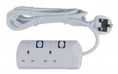
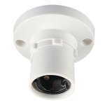
Personally, I would use something like a dual socket extension lead, which you appear to have retail in the UK (pic.) and there should be room on the faceplate to mount a suitable panel or batten mount lightbulb holder (pic.) next to the test socket, having sacrificed the second outlet.
Obviously, the plastic mouldings need to be amenable to this minor surgery and the necessary changes to the internal connections. You can see from the circuit, that the light bulb is wired in series with the Live lead to the test socket but that won't be how the wiring inside the socket is, as it comes.
This may seem over-the-top for a test device which you may never need again but the primary concerns are safety for you and the amp. and that begins with secure insulation all round the device and using rugged construction - hard to do unless you can adapt ready made items that are up to it. In any event, double-check your wiring and test it for correct continuity or not before powering up and keep any unsuspecting folk well clear when working with devices that are unusual or curious - nobody wants to be responsible for harming others.
There are several things to note about electrical safety when doing mains wiring, which you'll see if you search these titles and look at the many more examples and diagrams, some with adequate warnings, many without, on the net.
For constructors, all the wiring and connectors should be mains rated and leads should be double insulated, meaning 'as they come' in a 3 core cable - not individual wires as you might assume from the circuit illustration. All connections and individual wiring should be contained in robust, insulated boxes - well out of harms way. Whilst that diagram looks easy to understand, it fails to show what is needed for a lightbulb holder or where to mount one. However, the use of a spare extension lead simplifies a few things with a little modification. This preserves the safety of the device and only needs an existing lamp of some description with a bare lead to be connected into the extension box by drilling another hole and completing the wiring as shown but inside the box.
Personally, I would use something like a dual socket extension lead, which you appear to have retail in the UK (pic.) and there should be room on the faceplate to mount a suitable panel or batten mount lightbulb holder (pic.) next to the test socket, having sacrificed the second outlet.
Obviously, the plastic mouldings need to be amenable to this minor surgery and the necessary changes to the internal connections. You can see from the circuit, that the light bulb is wired in series with the Live lead to the test socket but that won't be how the wiring inside the socket is, as it comes.
This may seem over-the-top for a test device which you may never need again but the primary concerns are safety for you and the amp. and that begins with secure insulation all round the device and using rugged construction - hard to do unless you can adapt ready made items that are up to it. In any event, double-check your wiring and test it for correct continuity or not before powering up and keep any unsuspecting folk well clear when working with devices that are unusual or curious - nobody wants to be responsible for harming others.
Attachments
Thanks, yes the pair of bd911/12 are short between all three contacts, the 139/140 drivers are not, but i changed them because in circuit the pair of the blown channel showed different resistance to the pair on the good channel.
Fair enough.
As you show as UK based you could do worse than to get the BD911/912 and BD139/140 from CPC (part of Farnell). Don't buy parts from ebay as many are fake.
Thanks, The capacitor fed by the bridge, is that one of the 2 large blue 4700 40V [ C8 ]? can i test that one across the bridge pins. i already cut off the bridge so i can solder in a replacement tomorrow, there is no short across any of the 4 pins . does that mean the cap is ok?
The cap is probably OK but with a bulb tester there would be no problem even if it were not.
Because the amp runs on a dual or split supply (giving a plus and minus rail) there will be two reservoir caps... the big blue ones
My circuit doesn't seem to show much of the power supply at all but it will be text book stuff.
The short you read on the bridge shows that one of the diodes has failed.
 excellent.
- Status
- This old topic is closed. If you want to reopen this topic, contact a moderator using the "Report Post" button.
- Home
- Amplifiers
- Solid State
- QED A 240 CD Can Anyone Pls Help With Repair