Hi all,
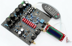
I just got my AK4497DAC board up-and-running.
The optical input works fine for 44.1KHz and 96KHz sample rates but nothing higher. I would expect it to go higher than that with the specs saying "PCM format supports up to 384K". Any suggestions on that?
I attached an Amanero USB board but I'm getting nothing from that at all. I'm guessing that the board needs it's own 3.3V supply.
The DAC board only has provision for pins 3 through 7 which doesn't include the 3.3V and GND pins on the USB board.
Do I need an additional 3.3V supply?
If so, I'm also guessing that I need to connect the 3.3V supply earth to the DAC board earth somehow? The DAC board supplies are all AC.
Off course the DAC board didn't come with any information.
Meanwhile some 44.1KHz and 96KHz listening tests.
Thanks, Dave.
Attachments
No sound from the Amanero USB input
Hi,
I found a source of 3.3V under the board (on a 10uF capacitor as suggested by the LT1963A datasheet). GND is one of the pins on the connector.
I'm still not getting any sound from the USB input though.
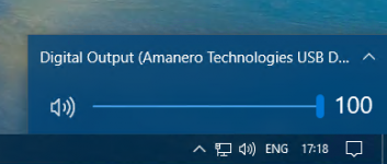
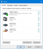
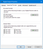
I've selected Digital Output (Amanero Technologies USB Driver 1.0.62) as the playback device in Windows as per the attached images.
I adjusted the Supported Formats tab as shown in the 3rd image. The Test buttons appear to be greyed-out though.
I've selected "USB" using the remote for the board. The "SAMRate" display flickers between "-----" and "DSD"
Any suggestions please? Am I missing something?
Thanks!
Hi,
I found a source of 3.3V under the board (on a 10uF capacitor as suggested by the LT1963A datasheet). GND is one of the pins on the connector.
I'm still not getting any sound from the USB input though.
I've selected Digital Output (Amanero Technologies USB Driver 1.0.62) as the playback device in Windows as per the attached images.
I adjusted the Supported Formats tab as shown in the 3rd image. The Test buttons appear to be greyed-out though.
I've selected "USB" using the remote for the board. The "SAMRate" display flickers between "-----" and "DSD"
Any suggestions please? Am I missing something?
Thanks!
Attachments
Seller says exactlly
Pls Note: the board is not compatible other version xmos usb card and Amanero usb card, Because I2S pin definition is different, so if you need USB Input, Pls buy the Xmos Version or Upgraded Verion , thanks )
So you must connect all 4 i2s lines, DSD on pin and gnd from Amanero to dac board with max 10cm 6 pin flat wire or maybe even suits if you solder this 6 pins and put it directly into dac board.... I dont see 7 pins as you wrote
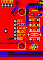
From left to right ... gnd DSD on MLCK, LRCK, BLCK and DATA.
Make a photo of your connection.
Do not feed 3,3V for amanero from dac, because it is feeded from 5v usb trought adp151 regulator in front of amanero board. If yes then you must cut output from adp reg.
Pls Note: the board is not compatible other version xmos usb card and Amanero usb card, Because I2S pin definition is different, so if you need USB Input, Pls buy the Xmos Version or Upgraded Verion , thanks )
So you must connect all 4 i2s lines, DSD on pin and gnd from Amanero to dac board with max 10cm 6 pin flat wire or maybe even suits if you solder this 6 pins and put it directly into dac board.... I dont see 7 pins as you wrote
From left to right ... gnd DSD on MLCK, LRCK, BLCK and DATA.
Make a photo of your connection.
Do not feed 3,3V for amanero from dac, because it is feeded from 5v usb trought adp151 regulator in front of amanero board. If yes then you must cut output from adp reg.
Last edited:
Hi ...
A cautionary remark first ... Your amanero board looks a bit different than mine in the text fields next to the output pins so it could be a different board you have.
However, normally the Amanero board gets its 3.3. VDC from the USB connection so under normal conditions it is not necessary to add an external power supply to the board. This can also be seen in the schematic here:
https://amanero.com/USB_E.pdf
In my experience it is, however, an improvement sound-wise to do so. BUT on my board it requires disconnecting the USB PSU e.g. removing the AD151 regulator (I think it is). It can be seen on the schematic.
Also please note that normally the 3.3 VDC pin on the amanero board is an OUTPUT - not an input. Thus, if the regulator remains in place you can get 3.3. VDC from the board for external devices like e.g. an clock isolator. I would NOT add 3.3 VDC to the amanero board if the AD151 is still in place as the two PSUs may counter-work eachother.
I reckon your amanero board should go into the rectangular field on the right bottom side of the DAC board, right? There are 5-6 pin holes there ... If this is the case I reckon one or more of these pin holes are GND - if this is so this is where you connect the Amanero board's ground. Not elsewhere ;-) And you have to make sure that the other pins on the DAC & Amanero boards are connected correctly (!)
And then, besides installing the driver for the Amanero you might also have to "flash" the CPU. There's a guide to doing this here:
Amanero Technologies
You flash the amanero with one of the config tools. Doing so helps setting up the amanero to your specific use.
Various config tools are available here:
Amanero Technologies
Finally, in case you have access to an oscilloscope this may help you see if there is an output from the amanero. Since the I2S output is one direction only you basically can verify that the amanero works as it should before connecting it to the DAC by looking at the outputs from the Amanero with an oscilloscope.
I suppose you already know this but there is a thread here on diyaudio dealing with tips and issues related to the amanero:
USB to I2S 384Khz - DSD Converter
Hope this may of help to you ... good luck in making it play ;-)
Jesper
Thanks Jesper.
I'll remove the link to the 3.3V supply and hope I've done no damage. I'll also read all the references you've provided.
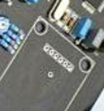
I've aligned the Amanero board directly over the DAC board and made the connections with a 6-pin PCB plug and socket.
I confirmed that the DAC board hole directly under the Amanero pin marked GND is indeed GND on the DAC board.
Am I correct in interpreting androa76's post as saying that the DSD.ON, MLCK, LRCD, BLCK and DATA may not correspond with the holes on the DAC board directly underneath them or is the the I2S somehow different?
I didn't see any seller stipulation regarding the USB card and assumed that I2S was a standard.
Thanks, Dave.
I'll remove the link to the 3.3V supply and hope I've done no damage. I'll also read all the references you've provided.
I've aligned the Amanero board directly over the DAC board and made the connections with a 6-pin PCB plug and socket.
I confirmed that the DAC board hole directly under the Amanero pin marked GND is indeed GND on the DAC board.
Am I correct in interpreting androa76's post as saying that the DSD.ON, MLCK, LRCD, BLCK and DATA may not correspond with the holes on the DAC board directly underneath them or is the the I2S somehow different?
I didn't see any seller stipulation regarding the USB card and assumed that I2S was a standard.
Thanks, Dave.
Attachments
Hi Dave,
You're welcome ... If you'll allow me a suggestion I would look up for sure which of the pins on the DAC board has which designations. And if they are different from the Amanero (and they may well be) then be welcome to post them here and I shall be pleased to help align them if I can. I'm not entirely sure what androa76 wrote so I cannot comment on that ...
You may also find this useful:
https://www.amanero.com/drivers/combo384-D.pdf
It is a preliminary datasheet for the Amanero board including description of the various pins.
I2S is a standard but the pin placement to my knowledge is not.
Cheers,
Jesper
You're welcome ... If you'll allow me a suggestion I would look up for sure which of the pins on the DAC board has which designations. And if they are different from the Amanero (and they may well be) then be welcome to post them here and I shall be pleased to help align them if I can. I'm not entirely sure what androa76 wrote so I cannot comment on that ...
You may also find this useful:
https://www.amanero.com/drivers/combo384-D.pdf
It is a preliminary datasheet for the Amanero board including description of the various pins.
I didn't see any seller stipulation regarding the USB card and assumed that I2S was a standard.
I2S is a standard but the pin placement to my knowledge is not.
Cheers,
Jesper
Connect to usb and mreasire if comes 3.3v out of reg and not 5v.
I'm only getting 0.5V at the 3.3V output of the Amanero board so I've probably damaged the regulator.
The Amanero output has disappeared from Windows 10 on my music server too.
I'll order another Amanero board. Less trouble than trying to replace the regulator.
No progress with the USB input
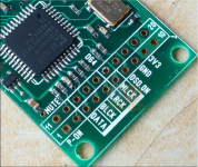
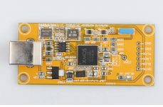
I finally returned to this project after receiving a new Amanero USB to I2S board. I’ve fitted it in accordance with the AK4497 DAC dual-chip decoder board pinouts as shown below:

as can be seen in this photo:

Still no output from the AK4497 board. The display shows:

I used my Oscilloscope to look at the outputs of the USB card while playing music. DSD.ON is zero volts. Here are the rest:
MCLK:

This 25MHz waveform could well be degraded by the 50MHz limit of my oscilloscope.
LRCK:

This looks to be 50KHz.
BLCK:

Looks to be 3.3MHz.
DATA:

While the optical input works fine I really would like to have the USB input working.
Androa76 said the seller of the board specified “XMOS or upgraded version USB to I2S” (the ad on AliExpress is no longer available) but every XMOS board I can find for sale has the same pinout as the Amanero board that I have.
Does anyone have any suggestions please?
Thanks, Dave.
I finally returned to this project after receiving a new Amanero USB to I2S board. I’ve fitted it in accordance with the AK4497 DAC dual-chip decoder board pinouts as shown below:
as can be seen in this photo:
Still no output from the AK4497 board. The display shows:
I used my Oscilloscope to look at the outputs of the USB card while playing music. DSD.ON is zero volts. Here are the rest:
MCLK:
This 25MHz waveform could well be degraded by the 50MHz limit of my oscilloscope.
LRCK:
This looks to be 50KHz.
BLCK:
Looks to be 3.3MHz.
DATA:
While the optical input works fine I really would like to have the USB input working.
Androa76 said the seller of the board specified “XMOS or upgraded version USB to I2S” (the ad on AliExpress is no longer available) but every XMOS board I can find for sale has the same pinout as the Amanero board that I have.
Does anyone have any suggestions please?
Thanks, Dave.
Hi if i see correctly it is that board for your dac and pins are
DATA, BLCK, LRCK,MLCK,DSD,GND.....you have DSD, DATA,BLCK,LRCK,MCLK,GND try my connection.
Thanks. I tried your connection originally. That's the direct connection of the USB/I2S card holes to the DAC board holes directly underneath them. It didn't work which is what started me off on this debugging process.
Yeah. It didn't work and I mistakenly thought it was because the Amanero card needed a 3.3V supply. That's when I damaged the board.
Have you been able to get DSD256 into this board?
cheers
T
- Status
- This old topic is closed. If you want to reopen this topic, contact a moderator using the "Report Post" button.
- Home
- Source & Line
- Digital Line Level
- Chinese AK4497 DAC dual-chip decoder board