It has been a long while since I looked at the 2200. I loaned two units out (years ago), one to Jack Bybee; another to Brian Cheney (VMPS), and neither have been returned to me, so I haven't seen one in years.
However, this amp is a good candidate for modification.
First locate any bypass caps that seem 'tacked on' or paralleled with other similar caps. Just remove them, except for one 0.1 uf or so cap in each board location. Any bypasses across power electrolytics should be removed.
Second, make sure that your feedback resistors (47K) are 1/2W Resista or Holco (old), nothing else will do.
This should get you started.
Striking - and giving indsight
It did hurt to remove all the speed. But the sound is more pleasing, smooth, calm and delicious. It kind off changed the face of the amp. I like the "new" - better - sound. The amp sounds inviting just after you turned it on. I think it is a good sign.
Will you give an short explanation ? - so I can search more effectively - what is nessesary speed ?
The feedback resistors are Holco H4. I dont no if its the old style type ?
Do you have any more proposals ?
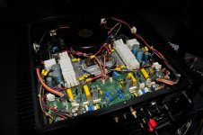
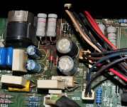
Hi I am new to this interesting forum, I recently purchased the HCA 2200 MkII, can you be more specific about the " caps that seem 'tacked on' or paralleled with other similar caps. Just remove them, except for one 0.1 uf or so cap in each board location" and what about the 47K resistors where are they, I am an electronic engineear my self so I think I can make some mods my self. Please also look at the attached pictures, can you tell me what is wrong with this resistors....
Thank you in advance.
p.s Sorry for my poor English but I am from Greece.
Thank you in advance.
An externally hosted image should be here but it was not working when we last tested it.
An externally hosted image should be here but it was not working when we last tested it.
p.s Sorry for my poor English but I am from Greece.
Attachments
Did you say you are an engineer.. you ask all the wrong questions. Questions an ee would not need to ask
Hi I am new to this interesting forum, I recently purchased the HCA 2200 MkII, can you be more specific about the " caps that seem 'tacked on' or paralleled with other similar caps. Just remove them, except for one 0.1 uf or so cap in each board location" and what about the 47K resistors where are they, I am an electronic engineear my self so I think I can make some mods my self. Please also look at the attached pictures, can you tell me what is wrong with this resistors....
Thank you in advance.
An externally hosted image should be here but it was not working when we last tested it.An externally hosted image should be here but it was not working when we last tested it.
p.s Sorry for my poor English but I am from Greece.
The majority of the poly - how many is that? There are quite a few ones. How about stripping all of them, and replacing them with a few good ones instead?
How is the best way to bias it? It's so compact, and to me it seems like the side needs to come off, in order to be able to measure - or is there a smarter way in?
How is the best way to bias it? It's so compact, and to me it seems like the side needs to come off, in order to be able to measure - or is there a smarter way in?
Vacuum it out first! Clean the contacts, both input and output. Finally, if you see a lot of 'extra' film caps across the main power caps, you can cut the majority of them out.
Thank you very much for the reply, I found the schematic online and from my understanding one must remove the film caps that are parallel to the main power caps, but the majority?? how many do I leave in place?? and an other thought if we decrease the value of the feedback resistors (47K) wouldn't the frequency response be increased ?? also does it mutters if the Holco is higher wattage (from my understanding no).
MKII
wattage for the 47k makes no difference (1w) say, I believe John was suggesting the H2 version. I just order the 47K from Texas Components. Changing the feedback value is not a good idea, tried it and did not get good results but you can do whatever you like. I would just remove the bypass polystyrene's and leave one for each. As far as the power supply bypass I found it best to add all the values that are in place and install one high quality polypropylene. I get very good results with the multicap PPMFX or better. I would take a really good look at the ripple under a load and make sure you main caps are still good. I have not seen a single one of the Richie caps they used in good shape. Element 14 has the a great CD cap. I usually use the 22,000uf 80v. Fitting in larger caps are not a option or at least it's more of a mess to fit and make no difference.
wattage for the 47k makes no difference (1w) say, I believe John was suggesting the H2 version. I just order the 47K from Texas Components. Changing the feedback value is not a good idea, tried it and did not get good results but you can do whatever you like. I would just remove the bypass polystyrene's and leave one for each. As far as the power supply bypass I found it best to add all the values that are in place and install one high quality polypropylene. I get very good results with the multicap PPMFX or better. I would take a really good look at the ripple under a load and make sure you main caps are still good. I have not seen a single one of the Richie caps they used in good shape. Element 14 has the a great CD cap. I usually use the 22,000uf 80v. Fitting in larger caps are not a option or at least it's more of a mess to fit and make no difference.
HCA-2200, not the 2200ii
Hello, sorry if I missed this, but I didn't see any comments about the earlier version of the 2200. That's what I have. But it sounds like the values aren't exactly the same . . .
The bypass clusters on the main filter caps are comprised of 3 large white block .1k 200V caps, and a smaller white block cap that is .01k 400(V) . . . with 6 yellow .01K100 Full PS caps in parallel.
A buddy was fixing the same model that I have, and he told me that the unit he is working on had the bypass "clusters" removed. There was no cap left, or put in the place. So I marked the +/- and location of each cluster before removing, and the amp seems to work fine. I "think" it sounds better, but I haven't listened to it enough.
I'm wondering if there is any "danger" in leaving the amp this way.
I would also like to know the answer to Kenwood61's question about the clusters in the series 1....Also does anyone know what changes were made between series 1 and 2 2200's, I read the 2's have 100,000uF caps in the PS and I know my 1 has 25,000. In short what series 2 mods can be applied to a series 1?
Discovered a simple but worthwhile renovation mod on my 2200ii, thought someone might benefit from this. I had noticed my power switch was deteriorating badly. When I took it apart I found badly burned contacts but also realised that it had a spare pair of contacts which are completely unused. Just move the lower pair of spade connectors onto the upper (unused) spades on the back of the switch and you effectively have a brand new switch. I had to put the damned thing back together again, so it wasn't quite so simple for me..
Hello to all,
I want to share some mods / restoration I did to my beloved Parasound HCA 2200 MKII, please follow the link below.
whatishifi: Restoring and modifing a Parasound HCA-2200II power amp.
The results are amazing")
I want to share some mods / restoration I did to my beloved Parasound HCA 2200 MKII, please follow the link below.
whatishifi: Restoring and modifing a Parasound HCA-2200II power amp.
The results are amazing
a friend of me want to enhance the input sensitivity (voltage gain factor) for approximately +6 db (MK-II version).
Is it possible to change the NFB resistors for higher voltage gain in the front end?
On a second device of the same model my friend want to perform a modify to get a "Unity Gain" unit in such a way, that such a variation arises like the cool follower from Andrea Ciuffoli - go to
http://www.audiodesignguide.com/my/Cool_Follower1.GIF
The main issue on this topology is the bad value for the so called power supply rejection ratio (PSRR).
Thank you for your advices.
Last edited:
- Home
- Amplifiers
- Solid State
- How to mod a Parasound HCA2200 Mk2?