I'm still trying to understand things, and am having difficulty interpreting the manufacturers specs.
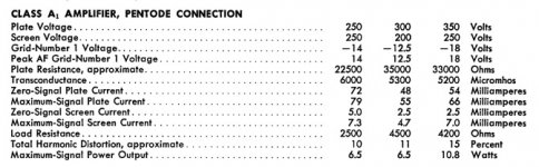
I found a load line simulator here: Triode / Pentode Loadline Simulator v.1.0 (20161216 www.trioda.com)
If I input the "Typical Operation" characteristics specified by the manufacturer, set the plate voltage to 250v, and the plate current to 80mA, the simulator says the grid bias is -32v; the manufacturer specs say typical should be -14v.
Am I misinterpreting some numbers? I don't see how the specs could be so different from the simulator's.
Attachments
Am I misinterpreting some numbers? I don't see how the specs could be so different from the simulator's.
Unless the model in the simulator is wrong or the G2 voltage is not correct. Also plate resistance should also be about 22K and not 100K.
The datasheet anode current at 250V at -14V bias is 72 mA, anyway.
Playing with the simulator it is unclear what Umax and Imax represent in terms of quiescent condition? They are just the max voltage and current in the picture. There is no obvious way to input the actual anode voltage and the actual anode current. With no information it is faster to get the datasheet, draw a loadline and calculate output power and 2nd + 3rd harmonic.....
Last edited:
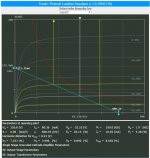
According to the specification its zero signal operating current Iq is 72mA at a plate voltage of 250V, screen grid voltage=250V and -14V control grid voltage.
Supposing that no bias cathode resistor is used then the supply voltage is Vplate+Iq*Rload=250+180=430V.
So the load line can be drawn from Va=430V going through the zero signal operating current point 250V,72mA (the red point) and ending up at Ip=172mA.
Supposing that no bias cathode resistor is used then the supply voltage is Vplate+Iq*Rload=250+180=430V.
So the load line can be drawn from Va=430V going through the zero signal operating current point 250V,72mA (the red point) and ending up at Ip=172mA.
The question is how one can input those points (i.e. 430V for Ia=0 and 172ma for Va=0) or just the required anode voltage and anode current. If you input them in Ua max and Ia max it doesn't work. These two values only seem to be the max voltage and current in the picture...
Then the choice of Ugmax and Ugmin also affects the final results.
It basically looks like trial and error....it takes forever for a newbie.
Then the choice of Ugmax and Ugmin also affects the final results.
It basically looks like trial and error....it takes forever for a newbie.
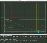
For example, 6L6GC pentode, to get close to the datasheet point and get:
Ua=249V
Ia=74.22mA
Ug=-15V
with the intecepts Va=438V for I=0, Ia=172mA for Va=0,
one has to enter:
Uamax=548V
Iamax=191mA
Ugmin=0
Ugmax=-30V
Us=250V
What numbers are these?? They seem to be only the max and min values that are displayed and to arrive to them there is some guesswork.....
Ua=249V
Ia=74.22mA
Ug=-15V
with the intecepts Va=438V for I=0, Ia=172mA for Va=0,
one has to enter:
Uamax=548V
Iamax=191mA
Ugmin=0
Ugmax=-30V
Us=250V
What numbers are these?? They seem to be only the max and min values that are displayed and to arrive to them there is some guesswork.....
the simulator says the grid bias is -32v; Am I misinterpreting some numbers? I don't see how the specs could be so different from the simulator's.
That 32v, (-)32v looks like the negative swing for max signal in a push-pull class A system with a (-)16 bias. So it's 32v PtoP. Good luck with the symming... Do you have it set up for PP but looking for SE numbers?
Last edited:
shakeshuck wrote:
"Am I misinterpreting some numbers? I don't see how the specs could be so different from the simulator's."
My question: Why are you using this "simulator" anyway? Why not just take the published characteristics
of the tube you want to use and do the graphics and calculations by hand?
"Am I misinterpreting some numbers? I don't see how the specs could be so different from the simulator's."
My question: Why are you using this "simulator" anyway? Why not just take the published characteristics
of the tube you want to use and do the graphics and calculations by hand?
According to the specification its zero signal operating current Iq is 72mA at a plate voltage of 250V, screen grid voltage=250V and -14V control grid voltage.
Supposing that no bias cathode resistor is used then the supply voltage is Vplate+Iq*Rload=250+180=430V.
So the load line can be drawn from Va=430V going through the zero signal operating current point 250V,72mA (the red point) and ending up at Ip=172mA.
I did what I read here:The Valve Wizard -Single EndedThe question is how one can input those points (i.e. 430V for Ia=0 and 172ma for Va=0) or just the required anode voltage and anode current. If you input them in Ua max and Ia max it doesn't work. These two values only seem to be the max voltage and current in the picture...
Then the choice of Ugmax and Ugmin also affects the final results.
It basically looks like trial and error....it takes forever for a newbie.
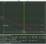
The simulator can be used to find operating point for classB. Then I drawn manualy the red load line for classA. The simulators parameters still are valid for classB. But now it is easy to take values for voltage swing that the OPT will allow and draw a classA load line in the simulator. It even gives figures for harmonic distortion now!
Attachments
shakeshuck wrote:
"Am I misinterpreting some numbers? I don't see how the specs could be so different from the simulator's."
My question: Why are you using this "simulator" anyway? Why not just take the published characteristics
of the tube you want to use and do the graphics and calculations by hand?
I was having problems doing it by hand - reading contradictory or unclear instructions, interpreting manufacturer's specs - so when I found the simulator I thought it might help me work out how to find the values I was after.
That 32v, (-)32v looks like the negative swing for max signal in a push-pull class A system with a (-)16 bias. So it's 32v PtoP. Good luck with the symming... Do you have it set up for PP but looking for SE numbers?
I think that is a fair observation on your part.
I was initially looking for PP, but noticed the software had references to SE. I have since spotted that SE parameters are shown for triodes, but not pentodes - so I don't know if the results are for SE or not.
The fact that the gain number is ridiculous makes me think something is wrong with it anyway.
I did what I read here:The Valve Wizard -Single Ended
The simulator can be used to find operating point for classB. Then I drawn manualy the red load line for classA. The simulators parameters still are valid for classB. But now it is easy to take values for voltage swing that the OPT will allow and draw a classA load line in the simulator. It even gives figures for harmonic distortion now!
That's not right. You have to have the right bias point and then draw the 2.5K line. In your picture that is 2.1K!
That software is like truly a trial and error software....
I think I've had a brainwave as to one place I may have been misunderstanding the spec sheet:
I couldn't work out how zero-signal plate current being 72mA and maximum-signal plate current at 79mA gave a useful usable range (thinking 7mA for the signal).
Am I right in saying that the 79mA is for signal on top of the 72mA - i.e. 151mA max current? That might help alleviate some of the confusion.
Am I right in saying that the 79mA is for signal on top of the 72mA - i.e. 151mA max current? That might help alleviate some of the confusion.
I believe it just quantifies the difference between the quiescent current ( 0 signal idle current) and what the tube actually produces with max signal. This illustrates the imbalance of power produced between the 2 conditions. Because if the signal was a perfect sine wave rising above and below the bias voltage then there would be perfect balance in current if the current produced below the bias voltage (during the negative cycle half) was reduced by exactly the same amount as it is increased going through the positive half cycle. So it illustrates that particular tubes's average current change imbalance as you increase the signal into the tube. It really means that as the signal gets bigger, near maximum signal input, the internal impedance of the tube goes down a bit and creates a higher max signal current, instead of always showing a perfect quiescent current (average current) which isn't supposed to change in a perfect Class A operating point. The negative cycle is supposed to balance the positive, but it doesn't do it completely at full signal input. You could call it the non-linearity of current production from 0 signal to max. signal.
Last edited:
- Status
- This old topic is closed. If you want to reopen this topic, contact a moderator using the "Report Post" button.
- Home
- Amplifiers
- Tubes / Valves
- Load lines and manufacturers figures (newbie)