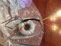
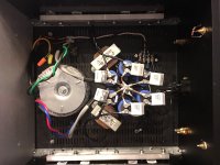
Just bought this transformer off ebay. Plan on using it for an F5T build.
I just realized I have no idea what wire are what on the primary side. This is a 0/110/117 transformer. I need 117.
I know which are the secondaries (brown/blue, red/green) but the primaries have me confused.
I've got 6 wires of on the primary side which makes sense. But I don't know which ones are 0 and which are 117. Two of the primary wires (brown and yellow)have double runs of wire in them.
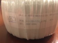
The datasheet does not match my wire colors. Perhaps this transformer is a custom job.
Anyone know?
I just realized I have no idea what wire are what on the primary side. This is a 0/110/117 transformer. I need 117.
I know which are the secondaries (brown/blue, red/green) but the primaries have me confused.
I've got 6 wires of on the primary side which makes sense. But I don't know which ones are 0 and which are 117. Two of the primary wires (brown and yellow)have double runs of wire in them.
The datasheet does not match my wire colors. Perhaps this transformer is a custom job.
Anyone know?
Attachments
You can use a DMM to measure the primary to find out 2 groups of 3 wires that are connected.
From each group, measure the resistances of all combinations of 2. The common color of the 2 highest resistance is the 0. Supposedly, the wire with the highest resistance to the 0 is the 117.
If you have a 6vac transformer like those for the vacuum tubes, you can feed the 6V AC to one the secondary pair and measure the VAC on the primary and deduct the primary using similar logic as above.
find which tappings are on which primary winding. Label them A or B for the two windings.
Then measure the resistance of the three alternatives A1 to A2, A1 to A3 and A2 to A3.
Find the highest resistance. That is the 0-117Vac tapping.
Find the lowest resistance. That is the 110-117Vac tapping.
Find the middle resistance. That is the 0-110Vac tapping.
Insulate the 110Vac tapping.
I suggest you insert each tapping into a separate receptacle of an insulated terminal block (safer with no loose wires flailing about).
Connect the 0Vac to Neutral
Connect the 117Vac to Live via a Mains Bulb Tester.
Switch on. You can now measure the voltages between all the other tappings.
That secondary voltage is too high if the secondaries are supposed to be 24VAC with a nominal 117VAC primary supply voltage. It sounds to me as though you have connected the incoming AC voltage which is probably 120VAC or even slightly higher to the 100VAC primary tap.
Contact the manufacturer with the specific part number of the toroid for the correct primary connections if in doubt. It looks to me as though the details you show in your first post have different wire colours on the dual primaries to what is actually on the toroid you have.
Contact the manufacturer with the specific part number of the toroid for the correct primary connections if in doubt. It looks to me as though the details you show in your first post have different wire colours on the dual primaries to what is actually on the toroid you have.
check the voltage across the primary taps.Switch on. You can now measure the voltages between all the other tappings.
This lets you check you have wired them correctly.
Is the 34V the DC voltage at the amplifier power terminals, when the amplifier is set to zero bias current?
Or is it the voltage stored on the PSU capacitors when there is no load on the PSU?
Measured at the last cap in the cap bank. The amp boards are not installed yet.
Additional options in this thread:
If you've got a signal generator and a scope,
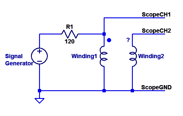
(You could also use a protoboard + NE555 oscillator instead of the signal generator)
If you've got a signal generator and a scope,
(You could also use a protoboard + NE555 oscillator instead of the signal generator)
- Status
- This old topic is closed. If you want to reopen this topic, contact a moderator using the "Report Post" button.
- Home
- Amplifiers
- Pass Labs
- Help me with this toroid!