Just wondering if speaker wire is okay for this, the common bare copper in clear plastic insulation variety? Split and twisted together, then probably heatshrinked over.
Or do the tinned copper strands (often used) serve some shielding purpose?
It's a short run, 160mm or so, and does not pass near the AC PSU, but does pass under the output transistors.
I can buy some different cabling if needed, thought I'd check first.
Or do the tinned copper strands (often used) serve some shielding purpose?
It's a short run, 160mm or so, and does not pass near the AC PSU, but does pass under the output transistors.
I can buy some different cabling if needed, thought I'd check first.
Just wondering if speaker wire is okay for this, the common bare copper in clear plastic
insulation variety? Split and twisted together, then probably heatshrinked over.
Yes, and twisted is best inside the chassis. Keep them away from the power supply wiring.
Solder all the strands carefully, or use crimp lugs. The Raychem is fine too, single or doubled.
Last edited:
Yes, and twisted is best inside the chassis. Keep them away from the power supply wiring.
Solder all the strands carefully, or use crimp lugs. The Raychem is fine too, single or doubled.
Thanks as always rayma, I went with the doubled Raychem.
Fast response was handy as I was just working on it now.
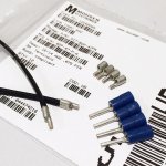
I used some cut down 3M copper lugs, and at the speaker terminal end they'll be wrapped and soldered directly.
Is it better that they are all twisted together or in L/R pairs?
Or no matter?
Attachments
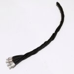
twisted
Good terminations are the most important part. I would keep the L and R twisted pairs
physically separate. Some amplifiers might have a problem with the parasitic cross-coupling.
Also a single well formed twisted pair will be less likely to interact with other circuitry.
It's hard enough to get just one tightly twisted pair right.
I used some cut down 3M copper lugs, and at the speaker terminal end they'll be wrapped
and soldered directly. Is it better that they are all twisted together or in L/R pairs?
Good terminations are the most important part. I would keep the L and R twisted pairs
physically separate. Some amplifiers might have a problem with the parasitic cross-coupling.
Also a single well formed twisted pair will be less likely to interact with other circuitry.
It's hard enough to get just one tightly twisted pair right.
Last edited:
Thanks again, I've made them into separate L/R twisted pairs now.
I will heatshrink L/R separately and maybe solder over the crimped connections thinly before soldering into the board since you say the terminations are important
What's the purpose of the individually tinned strands? Speaker wiring seems to often be bare coppper while most internal amplifier wiring I've seen has the bare strands tinned, often including small-signal. I've wondered if it matters.
My guess was tinning gives it more corrosion resistance in the long term, while not tinning gives more flexibility for non-fixed wiring, but that's just mechanical and I've wondered if there are electrical differences too.
What's the purpose of the individually tinned strands?
Tinning helps prevent corrosion, which copper will do quickly when exposed to oxygen,
causing poor connections. Gas-tight crimped connections on bare copper are ok.
Last edited:
Tinning makes soldering easy, so wire for use within equipment is often tinned. It makes little difference for wires which are to be clamped, so wire for use between equipment is often left bare. Simple twisted pair is fine for speaker wiring within equipment. If it doesn't run near the PSU it probably doesn't even need to be a particularly tight twist. I am not sure what the heatshrink is for - I would not bother. Keep some distance between the two channels; definitely do not twist them together!
care to elaborate as to why? at speaker level if channels interact because of wiring proximity can we regard the amp as stable?Keep some distance between the two channels; definitely do not twist them together!
There´s "proximity" and "proximity" ")
A couple parallel wires an inch away or more can have how much parasitic capacitance coupling between them? 1pF ... 5 pF? ... same as 0
Now if you tightly *twist* them, copper to copper may close down to 1 or 2 mm, with a nice plastic dielectric between them ... mutual capacitance can become 50 times as much, and become significant.
FWIW Radio transmitter gain stages used to be "neutralized" , meaning "made stable", by feeding back some RF out of phase and in a controlled way by using "gimmick capacitors" .... 2 short pieces of wire (and I mean *short*, 1/2" or less) , twisted together more or less tightly.
So wire to wire capacitance is a very real and useful phenomenon.
Notice value and position of the gimmick capacitor Cpk:
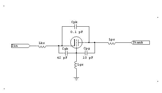
Is a 0.1pF capacitor significant?
You bet
A couple parallel wires an inch away or more can have how much parasitic capacitance coupling between them? 1pF ... 5 pF? ... same as 0
Now if you tightly *twist* them, copper to copper may close down to 1 or 2 mm, with a nice plastic dielectric between them ... mutual capacitance can become 50 times as much, and become significant.
FWIW Radio transmitter gain stages used to be "neutralized" , meaning "made stable", by feeding back some RF out of phase and in a controlled way by using "gimmick capacitors" .... 2 short pieces of wire (and I mean *short*, 1/2" or less) , twisted together more or less tightly.
So wire to wire capacitance is a very real and useful phenomenon.
Notice value and position of the gimmick capacitor Cpk:
Is a 0.1pF capacitor significant?
You bet
You sometimes see such a connection made by means of a "gimmick" capacitor merely consisting of two wires twisted together.
Interchannel crosstalk from speaker wires is more likely to come from inductive coupling.
Twisting a pair of wires is likely to raise capacitance but this should not be a problem. Given that the load is low impedance when compared to the line characteristic impedance it is line inductance which dominates - and this is minimised by keeping the wires close together.
Twisting a pair of wires is likely to raise capacitance but this should not be a problem. Given that the load is low impedance when compared to the line characteristic impedance it is line inductance which dominates - and this is minimised by keeping the wires close together.
I have already twisted them into separate L/R pairs as I said, and they will travel to the terminals separately without contact.
They pass under a heatsink, it's hot (Class A).
Wouldn't exceed the temp-rating of the insulation though, so I can skip that if not needed or undesirable for some reason. I didn't have a temp rating for the other wire which is why I considered some secondary insulation initially.
I'll keep some distance between them as advised.
I am not sure what the heatshrink is for - I would not bother. Keep some distance between the two channels; definitely do not twist them together!
They pass under a heatsink, it's hot (Class A).
Wouldn't exceed the temp-rating of the insulation though, so I can skip that if not needed or undesirable for some reason. I didn't have a temp rating for the other wire which is why I considered some secondary insulation initially.
I'll keep some distance between them as advised.
- Status
- This old topic is closed. If you want to reopen this topic, contact a moderator using the "Report Post" button.
- Home
- Design & Build
- Parts
- Speaker wire okay from relay to speaker terminals?