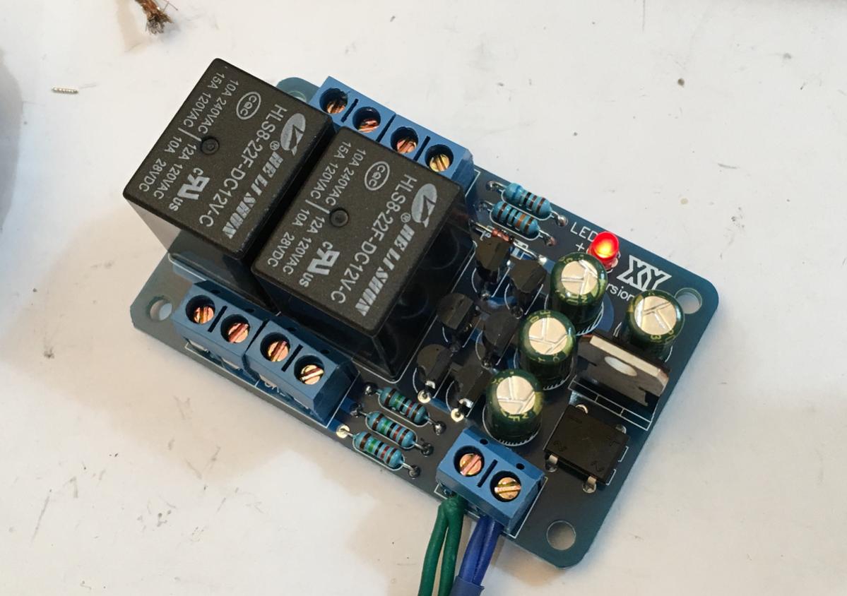
I just ordered this kit as it was dirt cheap. I assembled it and tested it and it works surprisingly well. I don't know what the circuit is as no schematic (uses 6 identical transistors) is provided but the 3 second delay works and the DC protect cuts out at about 1v to 1.5v DC if sensed on inputs. Takes about 5 seconds to re-engage once DC is removed. If one wanted to, just change out the relays for quality name brand ones. For under $5, these are very nice and work as advertised. There is no reason why one shouldn't have a speaker protect circuit given how cheap and easy it is.
Has anyone else tried these?
Audio Speaker Protection Board DIY Components Kit for Stereo

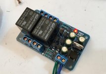
Here is my unit.
If anyone knows the schematic of how this works that would be great to share.
Has anyone else tried these?
Audio Speaker Protection Board DIY Components Kit for Stereo
Here is my unit.
If anyone knows the schematic of how this works that would be great to share.
Attachments
Hi, a bit more expensive than what you have there but comes with omron relays, I've built a couple, no problems AC 12-24V Circuit Speaker Protection Board DIY Amplifier Components Relay Kits
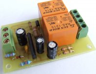
I bought and have used many of these ultra cheap protectors/delays.
But as with all relay contacts they may not isolate in the presence of high DC currents.
I did make a few changes to use 24V supplies.
The sch can be got by reverse engineering the PCB.
It is very simple and easy to do.
And don't fit the third 15k.
But as with all relay contacts they may not isolate in the presence of high DC currents.
I did make a few changes to use 24V supplies.
The sch can be got by reverse engineering the PCB.
It is very simple and easy to do.
And don't fit the third 15k.
I bought and have used many of these ultra cheap protectors/delays.
But as with all relay contacts they may not isolate in the presence of high DC currents.
I did make a few changes to use 24V supplies.
The sch can be got by reverse engineering the PCB.
It is very simple and easy to do.
And don't fit the third 15k.
Why not use the third 15k?
This board is actually quite compact and could even be used for a desktop headphone amp. Most headphones can take 1.5vdc (the trigger point) so probably better than no protection.
the third 15k is across the "timing" capacitor.
That can ruin the timing to such an extent that the relay does not trigger.
In my view using a simple RC from an unregulated supply is a bad timer. Adding in the third resistor turns a bad timer into a worse one.
If you were to run the isolator from a regulated supply which then turns it into a resonable timer, then you find that the effect on timing of adding that third 15k is not as bad and can leave you with an effective way of "tuning" the delay period.
But I just miss it out and tune the delay by using a suitable value of plastic film capacitor where there is space to accomodate such.
Using an electrolytic REQUIRES one to slowly reform it to well above any voltage it may see in future operation. One of the biggest risks of using an unreformed electrolytic as the timer element in an unregulated arrangement is non triggering because the 15k and the electro draw so much "leakage current" that the timer NEVER triggers.
Finally before you try any of these unknown (no build guide) contraptions, it is incumbent on the user to first understand how it works. Then critically assess it's ability to do the job you the user requires.
Last edited:
xrk
I do not know mentionet DC protector schematic but You can use my one from headamp, very simple few component one. To add extra feature as a supply use single diode half way rectifier and NPN tranistor with biased zener diode in the base and You will have fast OFF feature when transformer is OFF.
Regards
Attachments
the third 15k is across the "timing" capacitor.
That can ruin the timing to such an extent that the relay does not trigger.
In my view using a simple RC from an unregulated supply is a bad timer. Adding in the third resistor turns a bad timer into a worse one.
If you were to run the isolator from a regulated supply which then turns it into a resonable timer, then you find that the effect on timing of adding that third 15k is not as bad and can leave you with an effective way of "tuning" the delay period.
But I just miss it out and tune the delay by using a suitable value of plastic film capacitor where there is space to accomodate such.
Using an electrolytic REQUIRES one to slowly reform it to well above any voltage it may see in future operation. One of the biggest risks of using an unreformed electrolytic as the timer element in an unregulated arrangement is non triggering because the 15k and the electro draw so much "leakage current" that the timer NEVER triggers.
Finally before you try any of these unknown (no build guide) contraptions, it is incumbent on the user to first understand how it works. Then critically assess it's ability to do the job you the user requires.
It uses a 12v regulator - so is not unregulated. I agree an elfctrolytic is not best choice for critical timing.
I like this uPC1237 protection because it does not require separate secondary for protection. It works from the power amp transformer, but you must make your own pcbs, there is no kit. I made 10 pcbs and the photo of one of these is attached
DIYfan: Speaker protection with uPC1237
DIYfan: Speaker protection with uPC1237
Attachments
I don't use a secondary transformer for the 12v (or some people like 24v), just stick one of these cheap DC step down converters from your +ve rail (up to 35v) and you get an easy source to drive your protect circuit. If you are above 35v, you will need a different converter.
LM2596 DC-DC 4V-35V to 1.23V-30V Step Down Power Module Voltage Regulator 3A | eBay
LM2596 DC-DC 4V-35V to 1.23V-30V Step Down Power Module Voltage Regulator 3A | eBay

Exactly,is a switching regulator....It's a passive connection via a relay so not sure how the circuit of this protection circuit would affect the power amp rails. Or do you mean connecting a DC to D.C. boost effect on the rail? I can measure when I get the next chance.
Here is the seller's description in perfect Chinese English:
SKT Flyer Protection board
Features
The speaker protection board has the power delay (3 seconds) and DC protection (from the control voltage is about 1V) function, a simple circuit board, making easy, safe and reliable. With LED status display, when the protection light, the normal work time off. using 15A high current relay, suitable for the vast majority of amplifier board. Operating voltage AC 12-15V, requires a separate power supply.
After installation size: length 65mm x width 40mmx high 25mm . BTL circuit need two sets.
They don't mention loss of AC detection function.
I like this uPC1237 protection because it does not require separate secondary for protection. It works from the power amp transformer, but you must make your own pcbs, there is no kit. I made 10 pcbs and the photo of one of these is attached
DIYfan: Speaker protection with uPC1237
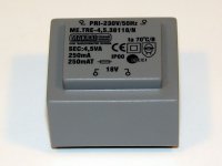
I use separated small transformer for the speaker protection. I cost approx. 2Euro, and PCB mounted.
Sajti
Attachments
- Home
- Amplifiers
- Solid State
- Speaker Protection Kit for under $5