Slightly off the wall one here but been reading a very interesting article from the mists of linear audio volume 3 by Steven van Raalte and comparing with the Bob Cordell vinyltrak article. In it he discussed an inverse resonance filter for dealing with the resonances that MM manufacturers build in to prop up the high end response, the end result usually being a bump in the response somewhere between 12 and 15 KHz then a 4th order roll off. Whilst this is
not a horrendous problem for us oldies who can't hear up there anyway it is predicted that this causes some unwanted time domain issues that the inverse filter addresses.
Now what would be nice is for there to not be any resonances at all in the audio band. Low inductance cartridges don't need the help so don't have the resonance. Therefore there is something about the design of the cantilever and/or the suspension that causes this. Once we know what it is then we stand a fighting chance of working out how to remove it. If it can be addressed then, with some changes to cartridge loading as discussed by both Cordell and van Raalte we can get a nice 1st order roll off to well above 20KHz and put the MM back on a level footing with MC models. Looking at this more deeply it appears this issue is one of those that was well known about in 1975 and many have forgotten.
So first step is to get a grip on the potential problem. Now I have 3 cartridge types I am interested in (as in own)
1. AT 150MLx 2K 450mH, 100-200pF recommended load
2. Ortofon super OM 1K 580mH 200-500pF recommended load
3. A&R x77 series (aka Garrott, aka Sumiko Pearl, AKA shelter 201 etc). 580 580mH
The last one is more of a 'project' as I have 4 cartridge bodies to perform evil experiments on and there are a wide range of replacement stylus types that will fit including the sapphire Jico SAS.
Now immediately I have run into some problems as both the Cordell and van Raalte cartridge models are over simplistic. Digging into this further shows the model is more complex and difficult to measure (Elliot). So we need to get empirical. More research shows that the best way to do this is to find a test record with square waves on and measure the response. Bother I don't have one of those, so £40 will have to go Ortofon's way as willing to bet CBS STR-112 costs $$$ these days. Once I have Jan's permission will pop in a diagram from the van Raalte article to show how the inverse filter cleans up the ringing on square waves. If I am right (unlikely but we all get lucky sometime) then you can record the output of the preamp and use audacity to mess around to find centre frequency and Q for the filter. When that is known we can see how much of a resonance is designed in.
Note: I am expecting to find that the ortofon and AT are not using too much in the way of mechanical cheating, but suspect the A&R does. Certainly both ortofon and AT have -3dB points at 30kHz which suggests the main cantilever resonance is way out the audio band.
Links. There are a couple of JAES papers that would help in this, but at $33 each I'll bumble around being empirical a bit longer.
https://linearaudio.net/sites/linearaudio.net/files/lte_vol3_1.pdf
Magnetic Phono Pickup Cartridges
http://www.kallhovde.com/advent/phono-pre-research.pdf
Here is the diagram I was talking about, thanks to Jan and (c) Linear Audio. This figure shows simulated cartridge square wave responses into a 47k load with 275pF total capacitance.
Trace A is the resonance superimposed on the signal. Trace B shows this output damped by the preamp loading. Trace D is the signal fed through an inverse resonance filter. There is some overshoot left, and the article explains how to deal with that, but I'm not giving it all away as its only €3.50 to get the whole article.
Trace A is the resonance superimposed on the signal. Trace B shows this output damped by the preamp loading. Trace D is the signal fed through an inverse resonance filter. There is some overshoot left, and the article explains how to deal with that, but I'm not giving it all away as its only €3.50 to get the whole article.
Attachments
Here is the diagram I was talking about, thanks to Jan and (c) Linear Audio. This figure shows simulated cartridge square wave responses into a 47k load with 275pF total capacitance.
Trace A is the resonance superimposed on the signal. Trace B shows this output damped by the preamp loading. Trace D is the signal fed through an inverse resonance filter. There is some overshoot left, and the article explains how to deal with that, but I'm not giving it all away as its only €3.50 to get the whole article.
I have an STR-112 but no MM carts these days. Frankly I don't see using it for anything, you could have it on indefinite load if it would help.
EDIT - Sorry it seems to have gone missing in the move, I have to open more boxes.
Last edited:
Interesting. Such resonance also often crops up in MC carts, presumably because the generator has relatively high inertia and the cantilever has spring, and is surprisingly often found in the audioband. Paul Miller's website catalogs numerous measured f response of MC carts, many of which show such features IIRC.In it he discussed an inverse resonance filter for dealing with the resonances that MM manufacturers build in to prop up the high end response, the end result usually being a bump in the response somewhere between 12 and 15 KHz.......
Not all MM carts have this resonance in the audioband: some manufacturers design for it to be above the audioband, and only have minor artifacts ( a bit of lift) at hf audioband which few of us here can hear anyway, let's face it.
Top end MM Ortofons and some AT MM carts have it centred above the audioband IME, and I settled on using these carts a few years ago because I use an unconventional pre-amp which avoids LCR electrical resonance, and I enjoy the sound of the results.
I think this is a better solution than inverse filters. Use a cart which has an ultrasonic resonance, be it MM or MC, and deal with the electrical interface so as to avoid an LCR resonance as necessary.
Because of the way effective tip mass is 'measured', carts with low spec effective tip mass have high resonant frequencies, IME. It correlates because measured mechanical resonant f is typically used to derive effective tip mass; wrongly so IMO, but that's another matter.
To avoid LCR resonance in MMs, I load the cart with a very low input impedance, near zero, and deal with the LR pole being wrong. This doesn't necessarily work well for all MM carts, but when it does IME it levels the playing field between MM and MC.
An upside of MM is then that a quality stylus is generally replaceable and cheaper.
Bill, the British Library subscribes to JAES, so if it's easy for you in London and you have a few articles to browse, that can saves fees/subscription.
Sort of, except programme material of a square wave does not produce a square wave shaped groove at all, of course !More research shows that the best way to do this is to find a test record with square waves on and measure the response.
A tiny sharp physical scratch or click, being impulse like, serves well IME. So long as one doesn't overdo it and rip the stylus off

LD
LD, sounds like you also follow the Cordell/Van Raalte idea of loading the cart hard and getting the RIAA HF pole for free at least conceptually. I also agree that picking a cart which doesn't need audioband mechanical uplifts. But given its easier than ever to measure these things a 21st century approach is needed. I also have (in bits) a very low input C phono stage which should help.
Good point on the scratch. B&K used to to that, although with a saw!
https://www.ortofon.com/media/15182/ortofon-series-500-mm-cartridges-brochure-page-1.jpeg shows in glorious unlabelled Axes the change in reducing eddy currents and therefore the self inductance.
What is becoming clear to be is that the usual 47k plus 100-400pF of most MM stages is just plain wrong as regards getting the best response. (with usual caveat about smug Grado owners).
Yes, probably to the max. My current MM pre-amp ('scuse punLD, sounds like you also follow the Cordell/Van Raalte idea of loading the cart hard and getting the RIAA HF pole for free at least conceptually.
) effectively presents a short circuit to the coils and is effectively current driven. Then external C loading is irrelevant. Yes, the 75uS pole is then 'wrong' and needs fixing, but I found a very tidy circuit way of doing that.Yes, cartridge coils are effectively one half of a transformer when one thinks about it, and the same principles of audio performance and losses can apply. Ortofon's MM armature is a very light hollow tube, and IIRC they have a patent for an eddy current reducing split in that which crops up on the higher end styli. IMO Ortofon's VMS generator is really MI.https://www.ortofon.com/media/15182/ortofon-series-500-mm-cartridges-brochure-page-1.jpeg shows in glorious unlabelled Axes the change in reducing eddy currents and therefore the self inductance.
Without opening Pandora's box, IIRC there might be some complication with Grado's MI coil arrangement as to empirical loading sensitivity despite measuring as low self-inductance. Or was it a dream ?
LD
I've never studied the Grado MI designs in detail. I know they have a tendency to act as aerials. Certainly VMS as described by Ortofon IS MI, although they call them MM. Any idea which Stylii have the split?
For those who haven't seen it https://www.ortofon.com/vms-cartridges-p-614 has some nice pics of the principle.
Calvin also has a nice cutaway diagram on his pages https://calvins-audio-page.jimdo.com/projects/phono-vinyl/vinyl-genera
EDIT: VinylEngine does have the 1975 patent as a download https://vinylengine.com/ve_downloads/index.php?ortofon_vms_patent_1974.pdf
Last edited:
An impulse in the groove will not have had RIAA pre-emphasis applied, so it will not produce an impulse out after RIAA equalisation. If you tune for an impulse out then you may have ensured that your equalisation is wrong?luckythedog said:A tiny sharp physical scratch or click, being impulse like, serves well IME.
An impulse in the groove will not have had RIAA pre-emphasis applied, so it will not produce an impulse out after RIAA equalisation. If you tune for an impulse out then you may have ensured that your equalisation is wrong?
I assume the idea is to compare the response to a mechanical impulse to that of an idea transducer, no equalization on either side.
For ascertaining the frequency and Q of the mechanical resonance to find out if this particular turd needs polishing then EQ doesn't matter. For ensuring the final adjusted output post RIAA is right, which would generally be flat to around 20kHz then a seond order roll off above that you need to either have an equalised signal or remember to account for it in analysis. Audacity and the like let us do things that would have been a big pain 30 years ago. I loved chart plotters, but I don't miss them!
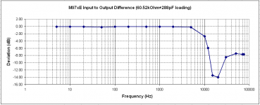
This is manual spot frequency measurement across the coil of an Shure M97XE.
An 100 Ohm Ro signal generator with a constant 4.91mVrms output, wired in series with the cartridge, feed a Hagerman Bugle RIAA preamplifier.
Cartridge:R:1K55, L:700mH.
0 dB refers to the measurement at 1KHz.
The collected data remained the same on all cases of cartridge position (Cartridge On Air, Cartridge lowered into Groove, Brush lowered, Brush raised, Stylus Force varied from 1 to 2 gr).
I guess the shown resonance is of electrical nature.
George
Attachments
An inductance of 700 mH with a 288 pF capacitor gives you a resonant frequency of about 11 kHz so you expect a drop in the response after passing the resonant frequency. High inductance cartridges require low terminating capacity.
I think the whole point is that it is more complicated than that. The electrical and mechanical circuits work together, in this case I assume there is a mechanical resonant peak that works in concert with the electrical roll-off.
I know the cartridge response is a combination of the mechanical and electrical response. I have a Shure V15VMR but the stylus is unobtanium. The Shure stylus had a stylus resonance over 30 kHz and the cartridge response thru the audio band was very smooth. The best loading was to minimize the load capacity. Shure now suggests a JICO replacement stylus with a stylus resonance around 20 KHz. That completely changes the needed cartridge loading.
https://sites.google.com/site/zevaudio/turt/cartridge-comparison-list/shure-v15v
https://sites.google.com/site/zevaudio/turt/cartridge-comparison-list/shure-v15v
Slightly off the wall one here but been reading a very interesting article from the mists of linear audio volume 3 by Steven van Raalte and comparing with the Bob Cordell vinyltrak article. In it he discussed an inverse resonance filter for dealing with the resonances that MM manufacturers build in to prop up the high end response, the end result usually being a bump in the response somewhere between 12 and 15 KHz then a 4th order roll off.
Something seems a bit odd about this idea. If the built-in resonance is to prop up the high frequency response, then why wouldn't an inverse filter un-prop up the HF response?
Same idea with a speaker. If you have a ported bass enclosure that uses resonance to extend LF performance, then why wouldn't an inverse filter give it the FR of a sealed enclosure?
Or is that the point, you would rather not have extended HF response if there has to be resonance to prop it up?
Or, maybe I am missing something?
Unless maybe we are talking about digital FIR filters?
Last edited:
Ray. Nice find. I'd been looking for some real data on the SAS stylus. Will be interesting to see how the sapphire versions they now produce compare*.
Ah https://sites.google.com/site/zevaudio/turt/digital-equalisation I see LD has already been here in a past incarnation
George: Not yet worked out why you have a trough rather than a peak in your measurement. I'm being very dim this evening.
*Other reason for interest in the SAS is because so many cartridges are compatible with the SAS-1 stylus so, despite it being expensive it does open up the possibility of being able to make a top flight performer for not too much. Given that AT has just renamed all its lineup and upped their prices by a high amount and the likes of the ortofon 2M black is $700 would be nice to get closer to the best for less.
Mark: You are missing something. look at the link Ray posted and the FR graphs. What you want from your cart+cable+phonopre combo is a 1st order roll off from 2kHz to 20+kHz to handle the RIAA eq. This is actually rare in reality as phono stages and cable have too much capacitance so you end up with a dip then a big peak then a 4th order roll of sometimes as low as 16kHz. Basically 47k plus 200pF of the average phono stage is not fit for purpose. SY in his 'equal opportunity' paper starts off showing that a possible reason why a lot of people thing that the AT-150MLx is a bright cartridge is because with too much capacitance you get a big HF hump, which younguns and lucky eldsters can hear.
One way to address this is to load down the cart so you get an LC roll off which is first order, but you then have the mechanical resonances to deal with. These are not hard in analogue but much easier in digital.
But of course reality is never quite that simple.
I should also note that there is no novelty here, just collecting together things that cleverer people than I have done but have been forgotten since the golden days of vinyl.
One way to address this is to load down the cart so you get an LC roll off which is first order, but you then have the mechanical resonances to deal with. These are not hard in analogue but much easier in digital.
But of course reality is never quite that simple
. I should also note that there is no novelty here, just collecting together things that cleverer people than I have done but have been forgotten since the golden days of vinyl.
- Home
- Source & Line
- Analogue Source
- mechanical resonance in MMs