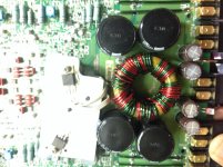
Good evening guys quick question, I would love to know the part placement of these two regulators for this amp (board PC-3085A) LM317T and LM337T, which one should be on the right or the left based on the picture provided.
I got the amp this way but I want to make sure they are placed properly, I can't see any part number markers. But just in case, which one goes nearest to the board label (pc-3085a Rockford corp). I can work from there.
I got the amp this way but I want to make sure they are placed properly, I can't see any part number markers. But just in case, which one goes nearest to the board label (pc-3085a Rockford corp). I can work from there.
Attachments
Thanks Mr Babin, I think one of the regulators are bad I'm almost out of the shop now but my test is it won't power up but when I removed the input voltages from the regulators the power supply powers up.
I didn't stop to check them one by one I just removed both feeder wires from the regulators.
I'll be back at it in the morning is there any other possible pointers that can be recommended Mr Babin?
I didn't stop to check them one by one I just removed both feeder wires from the regulators.
I'll be back at it in the morning is there any other possible pointers that can be recommended Mr Babin?
On this particular amp i had done repairs before where the LM317T had overheated and failed, turning brown and the amp wouldnt power up (well at least ive gotten 5 volts on the B+ rail and -4.2 on the B- rail).
im having the same issues but ive seen the tech after me had increase the heatsink to compensate the heat factor. I dont think the regulator is clamping down the voltage as its not getting hot but what i noticed is that it also supply power to the PWM in a loop back design (18volts to VCC pin 12).
Or could it be a protection error as these amps dont carry a separate led for notification?
Im not where the amp is now, im expected to make further test in the morning. The makeshift heat sink is covering a majority of the start up circuitry of the powersupply.
im gonna go ahead and changed the regulator as per prior repair before i remove the custom heatsink as its a bit of work as its silicone down to the board and other components.
i was making reference based on the schematic as ive seen its supplied from the outpin of the positive regulator. Probably im missing something If im incorrect.
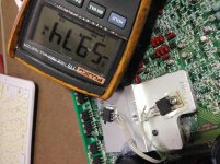
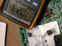
Morning Mr Babin, my findings now is when I remove the input from the LM337T I get approximately 60volts across the rails (center pin of both rectifiers)
When the pin is connected it's at 10volts across the rails.
I've tried another LM337T and it's the same result. Also at 60volts the power supply have an hissing sound (more like escaped air)
When the pin is connected it's at 10volts across the rails.
I've tried another LM337T and it's the same result. Also at 60volts the power supply have an hissing sound (more like escaped air)
Attachments
Good day guys, it seems the output of LM317T wasn’t making connection after the simple circuit modification to use a larger heat sink, my minus op amp volts was missing (-14.47). I’ve retraced my steps and found the fault as I said it was working before but didn’t want to lose another regulator to overheating.
- Status
- This old topic is closed. If you want to reopen this topic, contact a moderator using the "Report Post" button.
- Home
- General Interest
- Car Audio
- Punch 600.4 Regulators