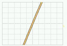
The Jitter of the measurement set up looped-thru (without Optical transmission loop), so Clock source (10MHz or 4MHz), Output 50 Ohm buffer, Trigger splitter and measurement set-up (Agilent DCA 86100A + HP 83484A 50GHz Scope) is 2.5pS RMS Jitter.
Below is the jitter of the complete set-up WITHOUT optical transmission loop.
50pS DIV, 2.5pS RMS Jitter
Below is the jitter of the complete set-up WITHOUT optical transmission loop.
50pS DIV, 2.5pS RMS Jitter
Attachments
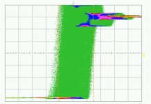
Complete SPDIF optical loop, using the Toshiba TX176 / RX176 devices, 4MHz Clock
Even though the results appear poor, it must be remembered that the Phase noise is HF and RANDOM in nature.
SPDIF receivers have good HF jitter attenuation, and Zero attenuation at LF, so it could be argued that the Ground & RF isolation offered by optical connection is worthwhile due to the reduction in LF Mains harmonic components. Random Jitter is always preferable to discrete components.
While Transformers might offer Good Ground isolation, they offer poor RF Isolation.
1nS DIV, Jitter = 750pS
Attachments
Hi,
since I was also concerned about toslink jitter i made my own test setup. Results are for TORX173 receiver and Hercules Fortissimo II computer audio card (transmitter unknown). Clock is around 2.8MHz.
It is very interesting that pins 5and 6 (case) of the receiver must be grounded, otherwise jitter is terrible. I also tested Infineon SFH551V receiver, but the results are much worse.
Here are my results: 3.9ns peak to peak jitter accumulated over 10 min of measurement. I am interested what the results will be after DIR1703 receiver (75ps jitter claimed in datashet)
Best regards,
Jaka Racman
Attachments
Great posts,
I do not have the means to measure but find paying close attention to the powersupply (and grounding) of the toslink units as having a more significant effect on "percieved" sonic performance ( less jitter).
Would you guys agree or is it similar in sensitivity to any other silicon used in digitalaudio?
I just realized this was supposed to be a reply in the thread about converting coax -> toslink.
http://www.diyaudio.com/forums/showthread.php?s=&threadid=1078
Anyway, its still interesting on its own and seems to draw attention so perhaps it should stay as is?
http://www.diyaudio.com/forums/showthread.php?s=&threadid=1078
Anyway, its still interesting on its own and seems to draw attention so perhaps it should stay as is?
Sure! I'm very interested in these kinds of tests.. since only those who have access to the very expensive analyzers can really give accurate results.
If you guys are willing/have the time, I'd really like to see some results downstream of various recievers.. or with ASR, or sample rate adjusting chips, different clocks, transformer input, etc... How much spare time do you have??")
Would be great knowlege for the DIY community..
Jon
If you guys are willing/have the time, I'd really like to see some results downstream of various recievers.. or with ASR, or sample rate adjusting chips, different clocks, transformer input, etc... How much spare time do you have??
Would be great knowlege for the DIY community..
Jon
Would you guys agree or is it similar in sensitivity to any other silicon used in digitalaudio?
I was surprised how much TORX173 is sensitive to decoupling. Usual 1uF ceramic cap I use in breadbording was not enough. I had to parallel it with 220uF OSCON. I did not use the recommended 47uH inductor.
Best regards,
Jaka Racman
To All:
A few questions about optical transmission:
What do people think of the sonics via optical?
What optical cables seem to work better?
Any recommendations for particular transmitters
and recievers (brand,model #, source) that work
better than average?
Thanks to all!
Fastcat
A few questions about optical transmission:
What do people think of the sonics via optical?
What optical cables seem to work better?
Any recommendations for particular transmitters
and recievers (brand,model #, source) that work
better than average?
Thanks to all!
Fastcat
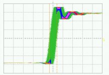
---------------------------------------------------------------------JohnW said:Complete SPDIF optical loop, using the Toshiba TX176 / RX176 devices, 10MHz Clock
1nS DIV, Jitter = 2578pS
John W et al
Without access to very expensive test equipment, what can be learned from and eye pattern test using a very wide band scope?
I have noticed that these vary very significantly from unit to unit in terms of time scale spread, ringing, and loss of symmetry. Also noise.
Are there good references correlating with test results?

Hi,
seems there is room for improvement particularly on the transmitter side. I have substituted Hercules sound card by Infineon SFH756V transmitter diode driven by HP function generator. Frequency is 3MHz, resulting jitter is around 1ns peak to peak, almost 4 fold improvement. Function generator has a rather slow 4ns transition time and around 125ps jitter.
When I will have some time I will try to implement peaking driver circuit.
I do not think that any improvement could be made by choice of different fibers, since proper polishing of fiber ends makes a far larger difference. For this measurements I used OKI fiber cut by scalpel, not polished. Even so, I had to pull fiber some mm out of the receiver, since SFH756V couples far greater optical power into fiber than typical Toslink transmitters.
Best regards,
Jaka Racman
Attachments

While jitter in the 1pS range its quite apparent using Sampling scopes, they normally cannot tell us anything about the Phase Noise characteristics, i.e. the frequency structure of the Jitter. Also by observing the cumulative effect of the jitter over many seconds we are really looking at longer term jitter in the sub Hz region, as apposed to the more audibly detrimental short term Jitter. However, its safe to say that provided the transmitter is driven by a decent stable Clock source, that the longer-term cumulative jitter bears a good relationship to short-term jitter, i.e. no Long term jitter = no short term jitter.
Some better / newer scopes have statiscal analysis software that uses the sampled data to generate FFT type frequency distribution plots of jitter.
RF spectrum analysers are more useful tools to characterise the jitter spurie, but normally don’t have the dynamic range to observe sub 10pS components without very narrow = long sweep times. Newer analysers combine swept RF and FFT processing to improve the sweep times. I use the older HP3585, but at best, it has a –120dB noise floor.
Maybe its time to develop a jitter analyser system for the needs of Audio designers that can analysis the system clock directly.
I have a “Paul Miller” jitter test system, my system is one of the very first, and is based around a National Instruments ISA ADC card. My version uses Crystal ADC card that aliases very badly with any incoming RF from the Unit-Under-Test, This RF show up as “spurie” which the software interprets as jitter components - while in fact they are only ADC artefacts. Once the UUT jitter levels are below say 150pS you have to be very weary of any components that system believes it sees. At this level, adding a 20KHz LPF to the ADC card “Removes” at least 100pS of jitter!
As the system analyses the audio output directly, it cannot distinguish between the causes of the spurie - be it Clock, PSU or Digital or Analogue artefacts. I’ve seen Paul on many occasions blame “jitter” as the cause of his observed “Spurie” around the 11.025KHz stimulus tone, where in fact they have been caused by digital processing artefacts, especially when measuring “Digitally Compressed” sources. These “Digital” artefacts should not be considered Phase Noise components.
The best Optical cable is no cable, so the shorter the better. Due to the Multi-mode nature of the Fibre, jitter is an inherent feature of the system. In a multi-mode Fibre, the light travels down the cable by bouncing off the walls of the cable, until it reaches the end of the Fibre. You end up with many steams of light at the receiver, each having taken there own path (read path length), some shorter, some longer, so the received pulse edges are no longer clearly defined = jitter.
If you want to make the most sensitive vibration detector I know of - get a length of spirally wound optical fibre and integrate the output – you can forget all about your Microphonic Valves.
Internal to the Toshlink receiver module is a diode detector who’s nA of current is amplified by 10's thousands to give Logic level outputs. This is the reason the internal screening (Case connection) must be connected to a very clean ground. In addition, due to the very high amplification, the receiver is very sensitive to PSU noise.
Hi John,
I do not think that plastic optical fibers are the weakest link in current toslink technology. First, we are dealing with LED and not laser diode transmitters . Second, I think that the main problem is integrated receivers and transmitters. If you try to implement photodiode and low noise receiver on the same silicon, you are bound to do some compromises. I think that discrete solution could give far better results. When I will have some time I will try to implement a discrete solution.
Posted below is measurement with identical setup as in previous post, but this time with 60m of fiber wound in bundle with 20cm diameter. My crude measurement shows increase of jitter from 1ns to 1.1ns., but this could be attributed to other factors (lower optical power in the receiver, different optical transition times of transmitter diode due to increased drive etc).
Your comments on microphonic properties of fiber are very interesting. This is something I have never heard before, but it seems logical. But I suspect that straightened fiber is less susceptible.
Best regards,
Jaka Racman
Attachments
Measuring Clock Jitter
Hi all,
Very interesting posts. I noticed that JohnW mentioned measuring clock jitter straight from the clock - it can be done simply by feeding the clock into a low pass filter (LPF) such as a 180R resistor and 10nF to ground which gives a cut off of around 88kHz. This demodulates the clock noise in the same way as a LPF would do on the output of a Pulse Width Modulated DAC in a CD player. The output of the LPF can now be viewed on a sound card using spectrum analyser software to obtain plots similar to this one:-
The noisy plot is of a Sony CD Player clock, the turquoise one of a commercially available clock and the purple trace is a MiniClock.
Best Regards
David
Hi all,
Very interesting posts. I noticed that JohnW mentioned measuring clock jitter straight from the clock - it can be done simply by feeding the clock into a low pass filter (LPF) such as a 180R resistor and 10nF to ground which gives a cut off of around 88kHz. This demodulates the clock noise in the same way as a LPF would do on the output of a Pulse Width Modulated DAC in a CD player. The output of the LPF can now be viewed on a sound card using spectrum analyser software to obtain plots similar to this one:-
An externally hosted image should be here but it was not working when we last tested it.
The noisy plot is of a Sony CD Player clock, the turquoise one of a commercially available clock and the purple trace is a MiniClock.
Best Regards
David
Hi Jaka,
I can not claim to know too much about optical transmission systems, why would a LED be worst then a Laser as a transmitter – is it just a question of power output, or is there a “noise” inherent to LED’s? I remember when ultra bright LED’s where first introduced, we used to pump them with many 10’s of amps nS pulses – they would then produce Laser light – suggesting that LED and Semi-conductor lasers are quite similar…
I’m very VERY surprised at the 60m test – far better then I would have expected – it would indeed seem to suggest that cable length is not a limiting factor – although this goes contrary to my past experiences. Do you know your cable is plastic or Glass Fibre – also can you confirm that your cable is multi-mode and not single-mode?
If your results are correct, it would suggest that 60m of fibre has the potential to perform better then Coax on longer cable runs – this is true in the Telecom industry, but I don’t believe they use cheap multi mode plastic Fibre for any of there longer runs.
I wonder how much straighten Fibre would help reduce the vibration sensitivity? The effect is cause by the minuet changes in light path length in Multi-mode cable as the light is internally reflected off the cables walls. I guess any spirally wound reel of multi-mode cable would still be subject to the same vibration levels, but the effect might be less with strengthen cable – it must be otherwise could you image the ocean noise induced on a long transatlantic Fibre run – but then again I guess they can’t use multi-mode…
The ideal solution for non-clock-locked SPDIF transmission is high power Laser Single Mode optical transmission – time to go to some of those many telecom bankruptcy auctions.
I also wonder what effect cable diameter has on vibration sensitivity. The Toshlink plastic fibre seems very thick in comparison to Telecom material.
If I can get hold of a greater selection of Fibre, I could make a simple phase detector and find out…
Going back to a statement I made earlier about the Paul Miller Jitter test system, that even though some spurie components around the Stimulus 11.025KHz tone are not due to Jitter – they will still have a detrimental effect on audio quality. So even thought the absolute jitter results might be incorrect (the components might not be due to phase noise) – a lower result still equates to better audio quality, provided the incorrect results are not due to RF aliasing in the measurement ADC.
is it just a question of power output, or is there a “noise” inherent to LED’s?
Power output might be a factor, transient behaviour as well (turn on/off characteristics) but one of the major differences between LEDs and lasers is the spectral purity of the output signal. I think the spectral impurity will add some noise, i don't know how much however.
Regards
Charles
Hi David,
If only life was so simple. Unfortunately you cannot compare PWM modulation with FM / PM. The real beauty of PWM is that you can demodulate it with simple filtering. The demodulation process with FM / PM is far more complicated – they need to be mixed with a carrier to recover the base-band signal. Jitter is PM or even FM modulation of the clock.
Its also worthwhile to point out that AM causes PM modulation, that’s how PSU modulation causes Phase Noise.
I’m still very unclear in my head, as to the exact differences between FM & PM. Sure, you can show me the mathematical differences – but I’m a simple soul at heart, and the Maths goes WAY over my wee little head!
Can anyone explain the differences between FM / PM in a langue I could understand – simple English would be a good start.
Hi John,
I am no expert in optical communications either, but I work in a company that deals with this business also. I had to look it up, but LEDs have around 40nm spectral width compared to 1-2 nm for lasers. This leads to pulse broadening because of chromatic dispersion (different wavelengths have different velocity because of differences in refractive index). But seems that chromatic dispersion is limiting factor in monomode fibers only. The fiber I used for testing is this one.
Best regards,
Jaka Racman
- Status
- This old topic is closed. If you want to reopen this topic, contact a moderator using the "Report Post" button.
- Home
- Source & Line
- Digital Source
- How much jitter...