Hi all,
Found the schematics in another forum, look simple enough and some rave about the sound of Rudistor.
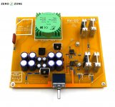
There is of course a Chinese ready made clone available.
My only concern is the 22 ohm output impedance not giving enough damping factor into low impedance headphones, so what you think?
Found the schematics in another forum, look simple enough and some rave about the sound of Rudistor.
There is of course a Chinese ready made clone available.
My only concern is the 22 ohm output impedance not giving enough damping factor into low impedance headphones, so what you think?
Attachments
Last edited:
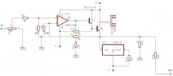
Looks simple enough indeed. I don't really see the point of using a Darlington buffer here though, especially with R10 as high as 10k (that's like what, 1.5-2 mA quiescent for Q1? you'd be better off using the '134 output directly). I'd rather be using a plain emitter follower using a single, faster power transistor (eliminating Q1) - maybe TIP31C or even 2SC5200 (I may prefer the former since older, less high-voltage types tend to be nice for Class A since what they may be lacking in ultimate fT they make up for in beta, and it should still be a good bit faster than the slow and oversized 3055). Make provisions for one resistor of like 22-47 ohms from opamp output (6) to Q2 base, and one small NP0 capacitor around 22-68 pF from opamp output (6) to noninverting input (2).
I don't see the point of R17 here tbh, maybe that one was supposed to go to V- instead? Then a 3-5 mA (maybe 10 mA) CCS would be better still, maybe with a few hundred ohms of series R.
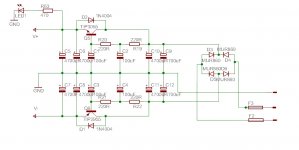
Not sure about the very simplistic cap multiplier "regulators" (which btw have transistor types swapped - Q5 should be the 2955 and Q6 the 3055). Their PSRR would be limited by rather finite loop gain as well as Early voltage (and a Class A amp is all you should ever run on one of these, given how slow they are), though I guess the rather generous capacitor sizes would make up for that. Consider using something with a whopping two transistors per voltage rail. Anyway, should be OK if you have the board space. I mean, speaker power amps tend to run on unregulated supplies, and if these things give you 40 dB of PSRR it'll be alright...
The 22R resistor R16 was included for loop stability reasons, as well as for providing rudimentary short-circuit protection. You should be able to get by without it, or at least with a much lower value in the 1-2 ohm range, once the little capacitor and base stopper resistor are added and Q1 is eliminated. (In simulation, I always got much better results stability-wise when going for a plain EF over a Darlington. No surprise there, less poles.) You can still add a resistor for short-circuit protection in series with Q2 collector, maybe 10 ohm 3 W.
AFAIR LM317 current sources appreciate some series resistance when run at higher voltages, else they may have a tendency to go unstable. Obviously at a nominal 125 mA, this could be no more than maybe 10 ohms, so I'd include maybe 3.3R 1 W and see how that goes.
Not sure whether one could easily hack all of these into the board as provided, even if it is quite roomy. Well, the layout is pretty bad anyway (or very oldschool at least) and would only ever fly in a Class A amp, what with the huge feedback loop area in the upper channel alone. That certainly didn't help stability either.
P1 = 50k seems a bit high given that OPAx134 input impedance nonlinearity is rather typical of JFET input parts - a 10-20k would be a better match, else maybe OPA1612 instead (but in this layout?).
I don't see the point of R17 here tbh, maybe that one was supposed to go to V- instead? Then a 3-5 mA (maybe 10 mA) CCS would be better still, maybe with a few hundred ohms of series R.
Not sure about the very simplistic cap multiplier "regulators" (which btw have transistor types swapped - Q5 should be the 2955 and Q6 the 3055). Their PSRR would be limited by rather finite loop gain as well as Early voltage (and a Class A amp is all you should ever run on one of these, given how slow they are), though I guess the rather generous capacitor sizes would make up for that. Consider using something with a whopping two transistors per voltage rail. Anyway, should be OK if you have the board space. I mean, speaker power amps tend to run on unregulated supplies, and if these things give you 40 dB of PSRR it'll be alright...
The 22R resistor R16 was included for loop stability reasons, as well as for providing rudimentary short-circuit protection. You should be able to get by without it, or at least with a much lower value in the 1-2 ohm range, once the little capacitor and base stopper resistor are added and Q1 is eliminated. (In simulation, I always got much better results stability-wise when going for a plain EF over a Darlington. No surprise there, less poles.) You can still add a resistor for short-circuit protection in series with Q2 collector, maybe 10 ohm 3 W.
AFAIR LM317 current sources appreciate some series resistance when run at higher voltages, else they may have a tendency to go unstable. Obviously at a nominal 125 mA, this could be no more than maybe 10 ohms, so I'd include maybe 3.3R 1 W and see how that goes.
Not sure whether one could easily hack all of these into the board as provided, even if it is quite roomy. Well, the layout is pretty bad anyway (or very oldschool at least) and would only ever fly in a Class A amp, what with the huge feedback loop area in the upper channel alone. That certainly didn't help stability either.
P1 = 50k seems a bit high given that OPAx134 input impedance nonlinearity is rather typical of JFET input parts - a 10-20k would be a better match, else maybe OPA1612 instead (but in this layout?).
Last edited:
- Status
- This old topic is closed. If you want to reopen this topic, contact a moderator using the "Report Post" button.