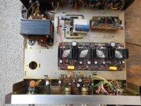
This is a great way to start the week, just found an amazing Sansui AU-222 in my grand parents' barn  , it looks perfect on the outside though a little dusty. The inside is surprisingly clean and looks very original. The pilot lamp is blown but the rest seems ok. I fired it up with my bulb tester and got all the right voltages across the board but it sounds a little tired so I'm planning a full restoration.
Beside replacing all the electrolytic caps what should I be looking for ?
I've been making my list of capacitors but the nichicon KG 1500µF filter cap is really small and doesn't really make the inside look as good as it should, would it be ok to fit a 4700µF instead and also change the rectifier diodes (if yes what specs should I be looking for as the original are 10D1, 1.5amps) ? Also there are two very small caps on the head amp board : 1.5µF, 15v BP, I can't seem to find them, any advice on what I should look for (50v 2.2µF was the closest I could find in the nichicon ES series)
This is how I found the little treasure :

, it looks perfect on the outside though a little dusty. The inside is surprisingly clean and looks very original. The pilot lamp is blown but the rest seems ok. I fired it up with my bulb tester and got all the right voltages across the board but it sounds a little tired so I'm planning a full restoration. Beside replacing all the electrolytic caps what should I be looking for ?
I've been making my list of capacitors but the nichicon KG 1500µF filter cap is really small and doesn't really make the inside look as good as it should, would it be ok to fit a 4700µF instead and also change the rectifier diodes (if yes what specs should I be looking for as the original are 10D1, 1.5amps) ? Also there are two very small caps on the head amp board : 1.5µF, 15v BP, I can't seem to find them, any advice on what I should look for (50v 2.2µF was the closest I could find in the nichicon ES series)
This is how I found the little treasure :
Last edited:
Nichicon KG caps are fine in this application but other manufacturers have equivalents too. I look at ripple current current rating which is the AC current capacity of the electrolytic when used to smooth rectified DC in power supplies. The rating also applies to AC (audio) current and varies proportionally with capacitance value, the grade of cap. and hence application. Ripple current capacity is also related to ESR which is the AC current "resistance" rating applied to smaller caps in decoupling, high frequency switching and power filtering applications.
Larger output capacitors generally deliver lower bass frequencies more efficiently and with less distortion. This can result in significantly more power output for a given volume setting and that could mean trouble, since the power output rating is small and there are are no protection devices apart from wire fuses. However, few people would use an amplifier of this size and age at its highest volume level and I would not expect problems with tripling the output cap. size. It will improve the sound significantly at moderate volume levels and that will be a great. With the amplifier's singleton input stage, it should sound very sweet too.
Sansui AU-222 Manual - Solid-State Stereo Amplifier - HiFi Engine
According to the manual, The output transistors aren't original and that may apply to the driver transistors too. There are only C601,602 1.5 uF caps in the preamp for input DC blocking. Using 2.2uF there would be fine and probably within the original part tolerance anyway. If you have film caps to replace the many 1 uF electrolytics, definitely do this where they fit easily within the lead spacing.
C001, the suppression cap. which clamps the power switching noise, would be tired by now and should be replaced with an X2 rated (mains safety certified) film cap. Apart from increasing cap. size by up to 100% generally, there should not be much else to do. There are lots of ways to spend money on any amplifier but I doubt that will make a simple, budget product sound like a High-end one.
Edit: The rectifier diodes should not need replacing. If you are looking for something that just looks bigger, standard 3A, IN5404-8 or equivalents should look the part. I would not suggest anything like ultra high speed SMPS diodes here.
Last edited:
That was what I was afraid of but as you say, this is definitely not an amp that will be pushed to its limits and if it is possible to improve quality at lower volume, no reason not to do it.
Is it necessary to increase the dimension of the rectifiers or will the original ones keep up with this modification ?
The service manual does mention the 2sc1030 (or 2sd247) as the original output transistors.
I read a thread from someone who restored one of these and he also mentioned changing the 1 µF electrolytics for film caps (wima MKS2). Even if these are "general film capacitors" what does make these so much better ?
For the suppression cap this seems to be a good replacement : http://www.mouser.com/ds/2/212/KEM_F3012_PME264_X2_660-535320.pdf
I might also change the speaker terminals because I noticed the speaker leads can easily touch.
To be honest, I looked for equivalents to SVO2 rectifier diodes and could not find any reference to them on the web. Without a specification, I guess they are nominal 2A rated diodes which could be replaced by any of the common IN5402-8 series 3A silicon rectifier diodes. For example, I have an AU101 Sansui model that is fitted with 1.5A rated diodes for 22W/8R rating and that has proven reliable since the early 1970s!
There are many stories here about the technical advantages of film caps V electrolytics. Some of those only refer to <0.001 % THD and others are just personal opinions of sound quality based on limited experience or without any credible proof. In practice, most of the advantages are more technical than practical but we find the electrolytics cheaper, smaller and easily available. The less obvious benefit of film caps is that they are stable at a wider range of temperature and perform more consistently across the audio bandwidth and beyond, with lower distortion. As long as their package is intact, sealing against contaminants from the environment, they will probably last more than a lifetime with original performance and that is a considerable advantage. There are more types too, with different dielectric materials and construction methods like metallized films, discrete film/foil layers, interleaving and lead attachment methods. This splits the performance debate even further.
The main technical difference is that being polarized, the common types of electrolytic cap. need to be biased such that that cap. maintains correct polarity at all times otherwise they won't retain their capacitance nor will they conduct AC in a linear manner.
Electrolytic caps slowly lose their electrolyte through unavoidable leakage and evaporation. As they are wet cells, their MTBF (mean time before failure) is much shorter than other capacitor types. Many are only specified for 1,000 hours operation at their ratings so the lifetime is finite but "rule of thumb" replacement time varies with individual technicians and local conditions of operation too. Consensus on when to replace is difficult since DIYaudio is people from almost every country, climate and audio design type but I think that in a linear system, 20 years is the minimum lifetime I would expect from good quality electrolytic capacitors in domestic environments. After that, at least a check of the loaded ripple level of the power supply caps with an oscilloscope is advisable. The smaller caps require a general decision, probably based on experience or in response to the owner's opinion of the sound quality. By contrast, the lifetime of electrolytics in Switched-mode power supplies can be unacceptably short. As little as 1-3 years is not unusual in my experience.
X2 caps also come in MKP types which are a usually cheaper and easier to find. The important detail is just the X2 rating. MKP types are also the preferred type of film capacitor for audio but they tend to be large and FKP types are huge - even 1 uF 250V is quite large and that increases problems for sensitive, small signal circuits. MKS is metallized polyester or mylar film, also known as MKT and similar to common "greencap" types. Perfectionists may criticize them but they are OK for audio in higher voltage ratings (IMHO ≥100V).
'Hope some of this is helpful but for some excellent, practical information and ideas, you should visit the large website of another Aussie member. There is a specific repair article there but the general construction projects, advice and facts are reliable and intended for a global audience. That should keep you occupied for a long time when you run out of repair projects - even if you do occasionally need Google Translate or such: Elliott Sound Products - The Audio Pages (Main Index)
Last edited:
Thanks for these explanations.
I finally used 2 IN5404 rectifiers which are also rated at 3A and so far they do their job perfectly.
I suppose that for an amp that is more than 40 years old there isn't any hesitation on whether to change the electrolytic caps or not. I don't think I ever had an amp of less than 20 years old so I'm used to changing the hole lot and than check for the ones that are still usable for other purposes.
I started reading some articles on the link you sent me and, and it has already proven very useful.
Anyway, I'm very pleased with the result of the many changes on this little Sansui, it sounds nothing like what came out of it when I first tested it. I read a lot about how good this amp really is and I can only agree.
I haven't got the time to take any pictures yet but maybe some day I will.
I know I started this thread a while ago but here are some pics of the little box of wonders after completely restoring it and with its new wooden case :


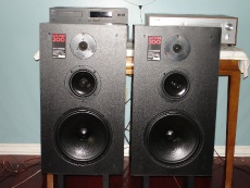
It sounds very nice on a pair of ditton 300, but it lacks a little detail, any suggestion on better speakers for a reasonable price for this one as I plan on keeping it ?
It sounds very nice on a pair of ditton 300, but it lacks a little detail, any suggestion on better speakers for a reasonable price for this one as I plan on keeping it ?
Ah, pictures - thanks for the follow-up.
Regarding speakers, are you certain that the lack of detail is down to the speakers, not the amplifier?
Celestion Ditton 300 are floor-standing (well, low stand mounting really), transmission line speakers - smooth sounding quality products and though prices are low, I think they would be expensive to replace. For new product, you might consider something at least in the KEF Q range like Q500 for much improved midrange clarity.
It would be difficult to suggest anything relevant from what is available used, in your local market, since you'll likely need to collect it from the seller yourself.
Hi Ian, I don't think it is the amp, because these speakers also sound a little dull on a pioneer SA-8800 that has tons of detail on a pair of ditton 66. I managed to get back some clarity by cranking up the treble to about +3 so that'll do for now as I don't have the necessary funds right now to go for expensive speakers.
Picowallspeaker, I haven't touched the crossover boards so yes that would be on my list if I keep these speakers, rewiring and new terminals have been done though.
I also have a Pioneer SA-500 (a) that I'm working on, it's similar in its simplicity but also sounds quite nice, I did replace all the electrolytic caps and will also change the small signal transistors in the pre-amp and phono stage as they get noisy after a few minutes of listening. I'm still looking for a metal plate for the selector switch that fell of and the previous owner threw it away, they are just glued to the plastic button and if you look on the internet most of these models have at least one or two missing.
Well, 500 A is the version with transistors in plastic package ? I have the 1st version, with metal case and output trasformer for the headphones. It has push buttons instead of levers.
I remember I did put a NP 0.22 uF at the input of the amp instead of the double cap arrangement pre-out/main-in. Some MKT caps in the phono stage (0.47 uF ?? ) instead of the electros... but usually I don't mind 'cos when compared to other phono stages these simple 2 transistor stages work well but not very accurate.
The same pre and amp combination can be found in the Pioneer C-4500 turntable ---the swithes are very sealed and difficult to polish
For the speakers...
I always suggest to keep the crossover out of the enclosure-
But also the enclosure, for me is the first thing that "goes" ( in the trash )
The midrange enclosure inside the enclosure - another bad thing
It sounds very nice on a pair of ditton 300, but it lacks a little detail, any suggestion on better speakers for a reasonable price for this one as I plan on keeping it ?
Hi Depaj
Nice vintage amp , I like it ,
---------------------------------------
-for best sonic results chose some hi-efficient LS with 16 ohm nominal impedance , those old low power amps likes them , and ...
- you can play with different values of VAS bootstrap capacitors( C807 & C808) to get better bass response , gradually raise the values from originally 10uF/25V up to max 47 uF/25V and listen the sound .
Best Regards
Hi Banat,
Thanks for the advice, that will be one of the criteria for the next pair of speakers, any model in particular or just any high efficient, 16 ohm speakers ?
I used nichicon ES for those but stayed at the original value at a higher voltage. I did upgrade the main filter cap from 1500 to 4700µF and this already gave it some more ease and punch in the low end.
Hi Banat,
Thanks for the advice, that will be one of the criteria for the next pair of speakers, any model in particular or just any high efficient, 16 ohm speakers ?
I used nichicon ES for those but stayed at the original value at a higher voltage. I did upgrade the main filter cap from 1500 to 4700µF and this already gave it some more ease and punch in the low end.
-I don`t know what you can find in your country from 16ohm hi-eff LS, but let`s say maybe some vintage Audax or some Cabasee LS will be OK ,
-that`s OK but try to mod values of those bootstrap caps too
quick question, a part from lowering the current flow to the speakers what does a higher impedance change to the tone ?
quick answer , it lowers amp distortion , improves DF , amp runs cooler ....
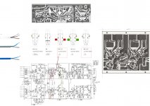
Sansui Au -222 Switch Wiring Diagram
Hi,
read this post and try to get an answer for fix my Sansui Au-222 amplifier.
I purchased a Sansui Au-222 parting out unit for restauration.
Meanwhile I got the lost three of the 5 toggle switches to complete the unit. Switch 5 and 6 (marked with rectangles in the attached sketch) are the parts in the unit.
SM Toggle Switch Parts:
S2 Tape Monitor,
S3 Stereo/Mono,
S4(a,b) Loudness,
S5 (a,b) Low Filter,
S6 (a,b) High filter.
I´m not as skilled as it might be nessesary to understand the tricky wiring of the toggle switches so i need help with a kind of wiring diagram or detailed Fotos from a reference maschine to go on.
Therefore I attache a drawing to illustrate the current situation. The drawing should be usefull to add lines for a wiring diagram for to the F-1083 Board. The tape monitor terminal must be done seperatly. The placement of the caps and resistors of Switch 2,3,4 shown on the drawing, is my result i suggest it will be right to the schema. If not please give me addvice.
I´m a newby with problems to translate the connections of the schematic diagram to the physical connetion on each pole of the toggle switches. Especialy the pole connections of the shielded wires. So have mercy and give me and the amp a chance.
Many Thanks for your feedback
Best regards
ps:
I´m looking hardly for the original knobs for the Sansui Au-222.
Nothing to fond in the bay. Perhaps someone in the communitiy have some.Thanks!
Attachments
- Status
- This old topic is closed. If you want to reopen this topic, contact a moderator using the "Report Post" button.
- Home
- Amplifiers
- Solid State
- Sansui AU-222 restoration