Hello.
I´m new here and also a real newbe to electronics.
I´m trying to settle for a design to build a gainclone and I think that I have decided to use a regulated power supply.
I have found a design for this that I like but when a was looking deeper in to it I kind of realized that I do not understand it...

When looking at these positive and negative rails, both LT1083 inputs are rectified the same way and meet at the middle. How does this work?
I can´t get my head around it...
And this type of design seems to be widely used.
Looking at an total different design with LM317/337 I can understand it better.
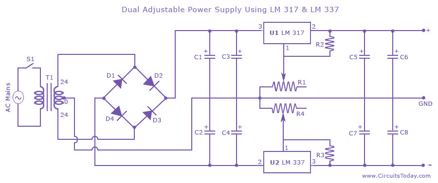
Here the inputs to LM317 and LM337 is rectified in oposite ways and the 337 is a negative regulator. This makes more sence to me.
I would like to design the LT1083 the same way, but that would need a negative version I guess.
Anyone who can explain this to a noob like me?
Thank you in advance!
I´m new here and also a real newbe to electronics.
I´m trying to settle for a design to build a gainclone and I think that I have decided to use a regulated power supply.
I have found a design for this that I like but when a was looking deeper in to it I kind of realized that I do not understand it...
When looking at these positive and negative rails, both LT1083 inputs are rectified the same way and meet at the middle. How does this work?
I can´t get my head around it...
And this type of design seems to be widely used.
Looking at an total different design with LM317/337 I can understand it better.
Here the inputs to LM317 and LM337 is rectified in oposite ways and the 337 is a negative regulator. This makes more sence to me.
I would like to design the LT1083 the same way, but that would need a negative version I guess.
Anyone who can explain this to a noob like me?
Thank you in advance!
If you look at the LT1083 circuit, you will see that it is two separate transformer secondaries creating two separate +30VDC supplies.
Since they are separate and isolated, the 0V (Gnd) output point of the upper supply can be connected to the +30V output point of the lower supply.
If we use that point as our Ground (0V) reference point, the other two output points will be at +30V (upper) and -30V (lower).
Likewise, we could call the -30V point "Ground" which would make the other output points in that circuit +30V and +60V. It is all the same.
The main thing is what chipamp are you planning on using and also what exactly are your voltage level and current requirements for your power level.
Here is a recent thread and similar discussion that you may want to have a read through in order to help further your education on a suitable regulation circuit.
http://www.diyaudio.com/forums/chip-amps/261125-lm3886-problem.html#post4037783
The LT1083 is a great regulator and I have one in one of my bench supply's but I haven't (needed to) tested it past 2 or 3 amps yet.
FWIW
Jer")
Here is a recent thread and similar discussion that you may want to have a read through in order to help further your education on a suitable regulation circuit.
http://www.diyaudio.com/forums/chip-amps/261125-lm3886-problem.html#post4037783
The LT1083 is a great regulator and I have one in one of my bench supply's but I haven't (needed to) tested it past 2 or 3 amps yet.
FWIW
Jer
Last edited:
Hello.
I would like to design the LT1083 the same way, but that would need a negative version I guess.
Other than a lower component count and if a dual secondaries transformer would somehow be unavailable, I don't really see why you would want to change the dual LT1083 (first setup) design to the LM317/LM337 setup (second setup).
It is possible, though, and you would indeed need to change one LT1083 out for a negative regulator.
However, it's noteworthy that negative low dropout regulators seem more prone to oscillations than their positive counterparts (at least the LM337 is). My preference would actually go to the first setup.
Last edited:
Hello.
I´m new here and also a real newbe to electronics.
I´m trying to settle for a design to build a gainclone and I think that I have decided to use a regulated power supply.
I have found a design for this that I like but when a was looking deeper in to it I kind of realized that I do not understand it...
When looking at these positive and negative rails, both LT1083 inputs are rectified the same way and meet at the middle. How does this work?
I can´t get my head around it...
And this type of design seems to be widely used.
Looking at an total different design with LM317/337 I can understand it better.
Here the inputs to LM317 and LM337 is rectified in oposite ways and the 337 is a negative regulator. This makes more sence to me.
I would like to design the LT1083 the same way, but that would need a negative version I guess.
Anyone who can explain this to a noob like me?
Thank you in advance!
The top one is easiest to understand if you consider it as two batteries in series with the mid point grounded. Each battery is + ... - yet when in series, the lower point is neg to ground...
Jan
Other than a lower component count and if a dual secondaries transformer would somehow be unavailable, I don't really see why you would want to change the dual LT1083 (first setup) design to the LM317/LM337 setup (second setup).
It is possible, though, and you would indeed need to change one LT1083 out for a negative regulator.
However, it's noteworthy that negative low dropout regulators seem more prone to oscillations than their positive counterparts (at least the LM337 is). My preference would actually go to the first setup.
I agree IF you have two separate secondaries, the first setup is measureably better.
Jan
I don't have equipment that can measure a difference.the first setup is measureably better
Some day I will get my FREX LNA built and see if there is a measurable difference.
Thank you all!
Thank you for giving me advices and for trying to help.
You make me feel welcome here, and not dismissed.
@ Jan:
You kind of cracked it for me with the two batteries. I feel that I get it now!
@ Jer:
Very interesting thread. Although I haven´t had time to read more than the first 4 or 5 pages. I will keep reading it all.
What do you think about the LT1083-design above? Will it also suffer from voltagr drop at higher current? Will a pass transistor help out in this design also?
I was also glansing at the 21st century Maida regulator.
But I kind of think it is a bit to complicated for my first amp project...
I think that it is fine!!
I have some LT1083's here and they are excellent chips!!!
They are very easy to parallel as well if you need to, so no need for a pass transistor. Just read the data sheet on them and some of the very excellent app notes using them.
LT has an example of an awesome dual-tracking bench supply that I am thinking about making.
Like I said I haven't had the chance to test them at higher currents yet.
The purpose of the thread I posted was that the OP was trying to use a transformer that had to high of voltage and so I had found the LM317HV but since this is not the case here the LT1083 is an excellent choice.
It has many vast improvements over the LM317 based LM78xx design.
Typically you really don't need a regulator at all for the chipamps as long as your supply voltage doesn't over exceed the chips maximum supply voltage ratings, this is why I had asked what chipamp family are you considering on using.
Regulators have been known to limit the current on Heavy Peaks and this sometimes can degrade the performance of the chipamp as well.
The 21st century Maida regulator is a High voltage regulator (+100V to +400V or more) where the regulator chip is kept floating and is referenced to a voltage very high above ground potential, it is not suitable for a chip amp design.
jer
Last edited:
Ok. Sounds good about the LT1083!
I´m considering a tube buffered gainclone (LM3875/76).
Gainclone amplifiers
This is more or less why I looked at the Maida regulator as I first was considering building a "normal" gainclone and pair it with a standalone tube buffer and that design needed 300v for the tube.
So, at this moment I´m thinking of pairing the mentioned LT1083 regulator with the above tube gainclone and feed the two channels with two 25vac 120VA toroids.
I´m only a little worried about the high voltages (35v in) for the gainclone part as I have read that the LM3875/76 is working best no higher than 27v...
There should be much of a problem running them at a higher voltage if you are using a 8 ohm load and do have a decent heat sink on it.
It is when you are using a lower impedance like 4 ohms is when it may struggle a bit and heat up more due to the increased current if you try to run it at maximum power.
This is way I tend to refer DIY'er's to have a look at the PA100 (parallel) version of running for at a higher power supply voltage, but is long as you aren't pushing it will work fine on a normal load.
Yes, many have made these statements but I have also seen many DIYer's use the higher voltage and say that they haven't had any issues and just watch the heat.
Tomchr has done a very good study on this in this thread,
http://www.diyaudio.com/forums/chip-amps/265771-lm3886-thermal-experiment-data.html#post4140882
jer
Last edited:
Ok, here comes one more stupid question...
The auther of the design (tube gainclone) gives a lot of advices about proper grounding.
Looking at the picture below raises an important question, even if it might be stupid.
Is it actually safe to connect power supply 0v to chassis ground?
Or have I missunderstood this completely?
Thank you again for all support!
I don't like the speaker going direct to the junction of the smoothing capacitors.
This "point" has very high charging currents passing across/through it and is the noisiest place inside the amplifier.
Take the speaker return wire alongside the speaker flow wire all the way to the 0r22 and then take the short route to the green link. Where the speaker Return hits the green link, label this as Main Audio Ground (MAG).
Now you can change the routing of the green link to the left of MAG. Instead of taking the long route to Chassis and then back to Power Zero Volts. Green should go direct from MAG to Power Zero Volts. This link is what prevents the charging pulses contaminating the MAG.
On the right hand side of the MAG the green is direct connected to the Signal Return at "S" This direct link works in a true mono installation.
If the amplifier is part of a multi-channel installation, then this link can have a Disconnecting Network inserted to attenuate the loop current that will occur.
This DN can have a switch to short out the DN if the system is impervious to loop current interference.
The DN must include a pair of power diodes connected in inverse parallel to conduct Fault current to "Earth" and a lowish resistance to minimise voltage difference across the DN.
Last edited:
PE protection is of course good.
However looking at all of mine comercial amps, non of them has grounded wall plugs.
And, as I´m living in sweden, many older houses has very few grounded wall sockets.
Now, in the room where my amp will be used I have grunded wall sockets. And I will of course use this ground to chassis.
My biggest concern was (is), what happens if the chassis isn´t properly grounded (PE). Like if someone moves my amp to a room with non grounded wall sockets. Will it still be safe to connect 0v to chassis?
@AndrewT:
So, if I put speaker return and Signal return to a MAG point and connect it directly to 0v (this is what you meant, right?).
If I then connect the smoothing caps to 0v also, it would be the same as before. Right? Nothing won?
What should I do with the caps. Connect directly to chassis ground?
Thank you in advance!
Wether or not a device is class I (earthed) or class II (double insulated), 0 V must go to chassis. Theoretically, you could float 0 V (or circuit ground) with respect to the chassis, but shielding will be far less effective. An interesting read on all aspects of grounding and the things that can go wrong is this article.
Your question could also apply to any commercial class I appliance with. And the answer is: no on un unearthed outlet, a class I appliance can never be as safe as on an earthed outlet.
A big manufacturer has the means to prove that its construction is compliant to class II. As a DIYer, you do not. Therefore, the only safe way for us to construct a device is one with chassis connected to PE (class I).
Last edited:
- Status
- This old topic is closed. If you want to reopen this topic, contact a moderator using the "Report Post" button.
- Home
- Amplifiers
- Power Supplies
- Voltage Regulator Question