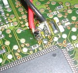
When removing a clock there was a resistor mounted across the clock output (see picture).
After listening to my CDP I have decided to move the LCAudio-stuff back where it came from, but this resistor dissapeared when it was removed. I measured it thow, and the value was 500 ohm.
anybody know what the purpose of this could be ??
After listening to my CDP I have decided to move the LCAudio-stuff back where it came from, but this resistor dissapeared when it was removed. I measured it thow, and the value was 500 ohm.
anybody know what the purpose of this could be ??
Attachments
I am sure...it was 0,5K ohm readout on my multimeter. I checked it out several times just of couriosity.
Didn't understand what it was....
Don't remember the color-code right now, but from another picture I got it seems like GREEN, GREY, GREY, BLACK, and with BROWN "alone" on the other side. But the quality of the pictures could have been better...
Didn't understand what it was....
Don't remember the color-code right now, but from another picture I got it seems like GREEN, GREY, GREY, BLACK, and with BROWN "alone" on the other side. But the quality of the pictures could have been better...
Lyra said:I am sure...it was 0,5K ohm readout on my multimeter. I checked it out several times just of couriosity.
Didn't understand what it was....
Don't remember the color-code right now, but from another picture I got it seems like GREEN, GREY, GREY, BLACK, and with BROWN "alone" on the other side. But the quality of the pictures could have been better...
it was very likely in series with the output of the original oscilator, driving the crystal
Guido
Wish I could help more, if it where a resistor from the colours you gave it would be 588R? maybe – but to the best of my knowledge you cant get a 588R resister – not in any E series that I’m aware of?
However, I guess the unit should work OK without it?
In any case, I would not worry about correctly terminating the clock – looking at the crude wiring from the clock board, its not as if it’s a controlled impedance… and who knows what the output impedance of the clock board is anyway?
I also don’t believe that adding an external clock to the DSP decoder in your DVD player is going to improve matters – if anything it can only make matters worst with extra noise due to external ground loops, mis-termination, and noise that is no longer Common Mode, Pls. let me explain: -
By removing the crystal from the board, still leaves the internal oscillator circuit in the DVD decoder, the fact that you have an external input, will not reduce the phase noise of the internal oscillator, PLL and clock distribution paths.
The DVD decoder IC spends the majority of its time decoding the MPEG video at Line and Frame rates – 50/60Hz & ~16KHz. If you where to run a phase noise plot of the Audio Master clock generated by the decoder, you will find massive amounts of 50/60Hz & ~16KHz spurie – these products are directly in the audio band!
With the very poor inherent phase noise of the DVD decoder, I would be extremely surprised if you would see any reduction by adding an external clock oscillator. Any sonic “Improvement” will be due to a change, but not reduction in Phase Noise (jitter).
Has anyone seen any “before & after” jitter results from upgraded DVD players that has an INTEGRATED PLL + Decoder? There might be a small improvement to units fitted with and external PLL clock generator such as from Burr Brown / NPC.
At least with the clock upgrade – the previous owner of the DVD player wasted their money!
- Status
- This old topic is closed. If you want to reopen this topic, contact a moderator using the "Report Post" button.
- Home
- Source & Line
- Digital Source
- What is this resistor ???