you will need to put some bias resistors in before the base of the transisorts, otherwise there will be no current to flow through the base to create any drive. Try again with two 1k resistors in the circuit, going (one each) from the right hand side of the first capacitor, to the power rails.
bigparsnip said:you will need to put some bias resistors in before the base of the transisorts, otherwise there will be no current to flow through the base to create any drive.
You don't HAVE to bias the transistors on in order for it to work. It will lower distortion if you DO but you don't need to if you just want to see it work.
The reason it doesn't work is that your basic bipolars only have 1-vbe drop from base to the load. That means your crossover "zone" is +0.7 - -0.7 or 1.4 volts. With the darlingtons, you have 2-vbe's on either end. So this is +1.4 - -1.4 volts, or 2.8 volts of dead zone. This is probably a pretty significant portion of your signal if you're driving it with an opamp with low supply rails. What are your supply rails and what kind of opamp are you using?
Do this to get it to work on your darlington version. Put a 1k resistor in series with 4 diodes (all in seried) in series with a 1k between your +vcc and -vee. Apply the signal halfway between the diodes.
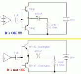
To Tip 142 To Tip 147
| |
+Vcc +---/\/\/\/-+--|>|--|>|--+--|>|--|>|--+-/\/\/\/--- -Vee
|
Signal In
you'll sort of have to turn this picture on it's side to see it right...
This is not a permanant fix!!! It's just a first step. With any real voltage rails, you'll cause thermal runaway when the devices heat up. This will be enough to get it running though.
--
Danny
azira said:
You don't HAVE to bias the transistors on in order for it to work. It will lower distortion if you DO but you don't need to if you just want to see it work.
The reason it doesn't work is that your basic bipolars only have 1-vbe drop from base to the load. That means your crossover "zone" is +0.7 - -0.7 or 1.4 volts. With the darlingtons, you have 2-vbe's on either end. So this is +1.4 - -1.4 volts, or 2.8 volts of dead zone. This is probably a pretty significant portion of your signal if you're driving it with an opamp with low supply rails. What are your supply rails and what kind of opamp are you using?
Do this to get it to work on your darlington version. Put a 1k resistor in series with 4 diodes (all in seried) in series with a 1k between your +vcc and -vee. Apply the signal halfway between the diodes.
To Tip 142 To Tip 147
| |
+Vcc +---/\/\/\/-+--|>|--|>|--+--|>|--|>|--+-/\/\/\/--- -Vee
|
Signal In
you'll sort of have to turn this picture on it's side to see it right...
This is not a permanant fix!!! It's just a first step. With any real voltage rails, you'll cause thermal runaway when the devices heat up. This will be enough to get it running though.
--
Danny
I'm using LM386
Richard C said:PicancoNet,
the best thing to do is provide your complete schematic with component labels and values, otherwise this could be very hard work.
Also, look at the schematics of other amplifiers and see how it should be done.
The complete schematic is above:
Attachments
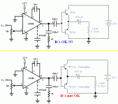
Richard C said:You could also get rid of the 1uF caps and include the transistors within the NFB loop and add emitter resistors.
Since he's got a 30V supply on the outputs, I have a feeling the LM386 is running on a seperate supply because it can't handle 30Volts of rail. The cap is probably to AC couple the output of the Op amp onto the output trannys. He would have to AC couple the NFB back to the op amp, but I bet in the actual circuit, he's got the NFB coming from the opamp which means the xover distortion is fully present. His darlington version probably really sounds like crap.
P:
I don't think that'll win anything to have the driver on different rails than your output since your output will only be as high as your driver will push.
azira said:
Since he's got a 30V supply on the outputs, I have a feeling the LM386 is running on a seperate supply because it can't handle 30Volts of rail. The cap is probably to AC couple the output of the Op amp onto the output trannys. He would have to AC couple the NFB back to the op amp, but I bet in the actual circuit, he's got the NFB coming from the opamp which means the xover distortion is fully present. His darlington version probably really sounds like crap.
P:
I don't think that'll win anything to have the driver on different rails than your output since your output will only be as high as your driver will push.
I´m using 15V for the LM386.
That's the point, your output stage won't be able to deliver a higher voltage than the input stage so why run it on 30V at all.
I can't see any merit in the approach you've taken even if it was made to work it wouldn't be very good.
All the answers can be found here
http://sound.westhost.com/amp-basics.htm
")
I can't see any merit in the approach you've taken even if it was made to work it wouldn't be very good.
All the answers can be found here
http://sound.westhost.com/amp-basics.htm
First things first... the LM386 has internal feedback from it's output, it's not the best choice device for this kind of configuration. You're going to want some global feedback to help with the crossover distortion (but you won't get rid of it.. as I have recently learned).
Secondly... you've DC isolated the bases and the emitters of the transistors so they have no references at all. That is probably causing some problems. You need to reference the bases some how. Put something like 10k from the NPN base to the +Rail and the 10K from the PNP base to the -Rail. That will "bias" the bases at 1/2 VCC and give a reference. This will still be in the same class of output if you do this.
Secondly... you've DC isolated the bases and the emitters of the transistors so they have no references at all. That is probably causing some problems. You need to reference the bases some how. Put something like 10k from the NPN base to the +Rail and the 10K from the PNP base to the -Rail. That will "bias" the bases at 1/2 VCC and give a reference. This will still be in the same class of output if you do this.
- Status
- This old topic is closed. If you want to reopen this topic, contact a moderator using the "Report Post" button.
- Home
- Amplifiers
- Solid State
- Why this amp does not function ?????