Dear Diyers!
I am currently building a DAC using CS43122
http://www.cirrus.com/en/pubs/proDatasheet/cs43122-2.pdf
and I have come across a tube output stage here
http://www.ultranalog.com/cdenhancer/cdenhancer2.html
I am just wondering if I build the 3a5 version, do I need to readjust any commponent on the circuit?
Thanks in advance
Arthur
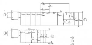
For this dac, you may omit the capacitor from grid to ground. It has nearly no energy in the band to 100 kHz, after whicht the tranny (sowter 8650 recommended) will filter strongly enough.
This dac has 1.33Vrms output. Be aware that you obtain 2.66Vrms out instead of 2V rms. If you wish, you can put small resistor ladders to lower the input, or load tranny to work with the 3a5's Rp.
By making one of each leg of the differential stage a pot, you can fine-tune the harmonic distortion (provided you can measure it). 10 dB or more of hd reduction can thus easily be obtained.
Thanks! Looking at the login name, I guess you must be the original author for that web page. Many thanks for your schematics and I must say that I have heard a lot of good review over the web.
>For this dac, you may omit the capacitor from grid to ground. It has nearly no energy in the band to 100 kHz, after whicht the tranny (sowter 8650 recommended) will filter strongly enough.
Do you mena the R7 = 150ohms?
>This dac has 1.33Vrms output. Be aware that you obtain 2.66Vrms out instead of 2V rms. If you wish, you can put small resistor ladders to lower the input,
Do you mean putting a number of resistors in series with R4, R2, R13 and R14?
> load tranny to work with the 3a5's Rp.
What do you mean by this?
>By making one of each leg of the differential stage a pot, you can fine-tune the harmonic distortion (provided you can measure it). 10 dB or more of hd reduction can thus easily be obtained.
Would an OCR be good enough to do this?
Thanks in advance
Arthur
")
No, I mean C1, C2, C11 and C12.Do you mena the R7 = 150ohms?
No, those are gridstoppers. By the way, I just remembered the 3A5's mu is 14, so 1.33 Vrms would work out to be exactly 2Vrms out. Great. Forget the whole argument.Do you mean putting a number of resistors in series with R4, R2, R13 and R14?
Optical Character Recognition?Would an OCR be good enough to do this?
Seriously, I have no idea what you mean by this. But try the design without fine tweaking first, and work your way from there.
Thanks for the link Frank. I was experiencing deja-vu but didn't feel like searching

HI Ackcheng,
just a tip or 2,
look carefully at how Remco wired up this stage on the lid of his cdp, the filament wiring is close to the edge of the lid, to help reduce hum. If you do build into a lid as Remco did it is a good idea to keep signal wiring length from dac chip to tube pins long enough for the lid to be raised high enough to permit comfortable working underneath - should there be a problem.
I don't know what type of caps Remco used in the PS, but I went for an all film cap power supply after staring with an electro supply - it's very detailed, but I now understand why some people prefer PIO caps or even electro's. The only problem with film caps is they tend to make the sound a bit 'hard' in comaprison to the relative bloated sound of electorlytics. Ofcourse it's a matter of taste, film caps offer tight realistic bass, and very well defined highs in fact they have more detail and resolution thean eny electrolytics I've ever tried. If you wish to try PIO's then I think Angela instruments have these at a reasonable price (albeit expensive if you think about it).
Let us know how you get on, damn thing makes the finest sounding cdplayer I've ever heard.
Thanks
Raja
dug up some more porn
signal wiring is shielded everywhere (microphone cable).
Filaments are on a LM317 regulator.
PSU tranny is switched on by a relay, driven from the player's 'standby' signal inverted.
PSU is a blend of electrolythics, PIO and film (if you need some, I have reserves).
Apply a bleeder resistor (~ 47k) over the PSU. This is not in the schematic since I only learnt it by building 1200V amplifiers. The bleeder empties the PSU when switched off (those blue film caps do not leak AT ALL, I've had a blow from one 72 hours after turning off the player). It also helps keep the voltage over the choke constant and thus eases the sound.
During testing this is more convenient:
An externally hosted image should be here but it was not working when we last tested it.
An externally hosted image should be here but it was not working when we last tested it.
signal wiring is shielded everywhere (microphone cable).
Filaments are on a LM317 regulator.
PSU tranny is switched on by a relay, driven from the player's 'standby' signal inverted.
PSU is a blend of electrolythics, PIO and film (if you need some, I have reserves).
Apply a bleeder resistor (~ 47k) over the PSU. This is not in the schematic since I only learnt it by building 1200V amplifiers. The bleeder empties the PSU when switched off (those blue film caps do not leak AT ALL, I've had a blow from one 72 hours after turning off the player). It also helps keep the voltage over the choke constant and thus eases the sound.
During testing this is more convenient:
An externally hosted image should be here but it was not working when we last tested it.
Hi,
that psu may be a good alternative, but I think you can also get good results using the one that Remco used,
bypass the rectifiers in his ps (3a5 filament supply) with 0.1uf film caps, I used schottky's and I would say that the benefits of schottky's with bypassing are definatley worthwhile.
Also I used 3a5's from Tube-shop (not a plug), they supplied me with raytheon 3a5's from the 1950's.
Getting hold of an az1 may be a bit more tricky, i'd love an old meshplate version if I can get one. Finding a socket can be tricky too, i still haven't bought one. Although I haven't made comparisons with other rectifiers, I love the az1, sounds good and looks nice!
Also you can try putting a low impedance cap at the filament pins of the tube socket, I used a couple of 16v 100uf black gate fk's, they do make a difference. But be warned you start messing with the character of the setup, the sound becomes 'hard', well and good if that's what you're looking for........
By the way I don't know the technical implications of it but I have no resistors in series with the diff output either, sounds great. Haven't done any measurements to find out whats going on (would need to know how), further Remcos advice a friend of mine has given me a scope to keep - 30mhz dual trace.
The choke I used is from maplins in the UK very cheap but does the job well enough, only around £7 ukp!!! I suppose there may be benefits to using more exotic chokes, perhaps Ultranalog or Frank can enlighten us to any experience they may have had with more upmarket chokes in the psu?
Thanks
Raja
Dear Ultraanalog,
When you say "For this dac, you may omit the capacitor from grid to ground"
Do you mean just leaving the connection between R4-gnd, R2-gnd, R13-gnd, R14-gnd open? I guess it is not quite right to join the these connection together otherwise the grid will be grounded.
Arthur
When you say "For this dac, you may omit the capacitor from grid to ground"
Do you mean just leaving the connection between R4-gnd, R2-gnd, R13-gnd, R14-gnd open? I guess it is not quite right to join the these connection together otherwise the grid will be grounded.
Arthur
HI,
No, I mean C1, C2, C11 and C12 "quoted from ultranalog"
Just imagine those 4 roll off caps aren't there, the wire carrying the signal will go directly to the corresponding pin of the tube socket, without having a cap bridging it to ground.
As you said yourself, you don't have to compensate the cap with a 'short' of any kind to ground, you won't be hearing music!
What Remco is telling us is that the opt's provide enough high frequency roll-off themselves without the need for the above caps. I've removed these myself and the differnce to my ears is obvious, I prefer the sound without the caps....
Which opt's will you use?
Thanks
Raja
Hi,
I don't see the benefit of adding another solder joint into the mix, this would negate the use of the higher quality wire. I'd rather stick with the original wire, than cut it and make another joint, in my experience you can hear the difference in even an extra solder joint, it's small but it does exist. For me to do this I'd unwind the tape around the winding and see if I could de-solder the supplied wires and attach the new wire directly to this point, overtaping again as necessary.
Mind you they do sound ok with the supplied wires!
Thanks
Raja
Thanks! I will stick with the original then! Actually, I have the same experience as well. When DIY my preamp, I prefer to use the components leg for connection as much as possible, instead of cutting it short and use silver wire with multible joints!
Thanks very reminding me!
Thanks very reminding me!
Hi,
The 3a5's are microphonic, but it doesn't seem to cause too many problems for me whilst listening. If you are having problems that are excessive, check layout, I'm no expert - Take a look at distance between tubes and any magnetic fileds. Also length of wiring from filament supply, best to keep these sort of things reasonably short. Also length of wiring B+ to tranny, and then tranny to tube..... The Guru's here would be able to provide better explanation, but I have a feeling that failure to implement some of the above or take care with layout could lead to oscillation.
Thanks
Raja
- Status
- This old topic is closed. If you want to reopen this topic, contact a moderator using the "Report Post" button.
- Home
- Source & Line
- Digital Source
- cs43122 tube output stage help - based on cdenhancer II design