Well, after using an HE-15 in a sealed design for awhile, I am stepping out. I have come up with a design to build a sofa table (the kind you put in back of the sofa) sub with massive capability. In looking at the ported designs of this driver, as succesful as they are, seem to underutilize this driver at normal port frequencies. Specifically, it has been challenging to broaden port area enough to really minimize port compression for this 6 liter driver. 2-6" ports would be great, but the port lengths (60" or more for 18 HZ extension) would support 100HZ + pipe res problems, etc, etc. They would be impractibly large, adding 2.3 cf just for the ports, assuming you could fit them in.
Look at the link below for the patent description of Powerport.
So in a roughly 200l cabinet, Fb=18, approx inside dimensions 12w x44l x 26tall, I am proposing 2 powerports running vertically on each side of the sidefiring driver, exiting at the top of the cabinet. Using Unibox, 2-6" ports would need to be 60" long each, an acoustic mass of 105kg/m^4 for each one. Using the powerport software obtained some time ago from ThomasW, using a 3" foam filled pvc connector, concentrically located, to connect the 8" diameter wave guides, each port will be approx 28" long. For each port, one wave guide to be mounted to the bottom of the cabinet, the other mounted at the exit on top of the cabinet. The resulting output should (theoretically) benefit from port area 50% greater than a single 6" or 2-4" (33% reduction in port velocities). At 1000 W the port output (and noise reduction) would be greatly enhanced, though at 100W, no real benefit.
Having the driver mounted on a large face (firing into the sofa potentially) will present bracing and resonance damping challenges, and the driver will only have 2" to breathe at the back (10" mounting depth in a 12" dimension). Since the ports exit on top of the cabinet, there can be no port noise, none. Any port noise would be noticeable in the sofa location I think. There is always the option of turning the cabinet upside down and this may well be a smart design change. I was just planning the ports into the cabinet aesthetics, with some nice carved feet on the bottom, Heavy Glass top, I am trying not to make this look like a sub, a secondary consideration. A sub man and wife can both admire.
As far as construction, I will turn the wave guides on the new lathe. Woodworking knowledge/tools is no problem. The 6" PVC will sit in the cabinet mounted on a brace with a flair routed on the reverse input side, required for the powerport.
This is a sketch of my idea, and I am making a drawing now and would like to get started. Tell me what you think. This will not be a simple project, and will be a result of several months of learning and research. If there is some interest I will post photos as work progresses.
I am unable to locate the powerport software on-line, maybe ThomasW can help, or if you want it just e-mail me, it is an excel file.
Here is a link to the patent office with some interesting reading from Polk:
MichaelPolk Patent

Not to discourage you
You might want to reconsider building a subwoofer that you can't move around the room. I just built an ebs endtable and it kicks some but in the low end, but is disappointing in the mid bass. It is great for movies, but is too easy to locate when you listen to music. My next subwoofer will be sealed/front firing.
You might want to reconsider building a subwoofer that you can't move around the room. I just built an ebs endtable and it kicks some but in the low end, but is disappointing in the mid bass. It is great for movies, but is too easy to locate when you listen to music. My next subwoofer will be sealed/front firing.
Yes, there is some compromise when you are trying to build a location specific sub, not a great way to set out.
But maybe with predominantly direct radiating positioning, close to the listening position (sofa table), these issues will work out. I know many people who make a coffee table with some success. Is this usually a bad idea?
This will be parametrically EQ'd with the BFD anyway, so maybe there is hope.
C'mon critics, I know you are out there. Look at the program and patent and tell me whether there is plausibility in this idea.
Michael
I looked at the PowerPort concept and decided it was too much work (or more likely I was too lazy....) Note I can upload a copy of the program files if people are interested.
My original ported HE-15 design using a single flared 6" port has survived the test of time. To this day it contiunes to amaze visitors with it's effortless and detailed output.
Now obviously it's not in the same league as a dipole or IB sub. But I will say I've never heard a conventional 'box' sub regardless of cost or design that sounded any better.
I've driven this sub to literally house shaking SPL's (note that the Fs of the house itself appears to be ~16Hz), and never have there been any indications of port compression or chuffing.
If the 6" AeroPort flares are still available, I recommend trying them. They allow a single 6" flared port to flow as much air as a straight 8" port. They also keep the port a 'reasonable' length.
Hello ThomasW
I remember you saying somewhere, that you wonder about that driver's performance in say a larger box than your 180l AS15. Besides the weight consequence, that would also create a larger saddle in the response, not a bad idea maybe, Comments?
I saw your clio resting of your project, but I don't know much about these curves (how to interpret them) and what they represent. Is there an output curve somewhere that shows the spectrum at reference outputs? I saw one TC sounds project from a few years back, tuned to 23 HZ, that showed obvious port losses with 2-4" ports, and he even recommended doubling his port area (if it were feasible).
.
Smaller ports of the same area is disadvantageous, comparing this with a single 6", but not much.
So it looks like some work to only modestly improve the low end. Since you have seen powerport, and know what it is trying to do with it's waveguide theory, would a 50% increase in port area be beneficial when it comes to 16HZ, 10HZ?
BTW, I found a 1.5 inch roundover bit and I'm planning on making flairs as required for the project
Ambitious project, I like it.
I think ThomasW sent me this same info when I was in the early stages of building my Maelstrom Sonosub and I wanted to do the Power Port thing, but I was going to make mine moveable (up and down) in a vertical port, but I couldn’t get a port at the bottom of the enclosure where it needs to be for the Power Port design to work properly. As ThomasW stated I also found the Power Port to be too difficult, if you read the white paper you will discover that the stem diameter and length as well as the proximity of the valve head to the opening is all interrelated and critical for proper operation. I decided that turning several different valves with different stem diameters was too much trouble for the little gain you get, so I just used the valve idea as a Port Plug and a decorative finial to dress out the top of an ugly Sonotube. CAT makes some custom subs just like what you are describing except without the Power Port, but if your sub will be out in the middle of a room with no wall boundaries close by (like a coffee table sub) then you will be wasting a lot of SPL and you wont be able to tweak it much.
You could just run the ports horizontal so they will fit in the enclosure, also have you modeled the drivers you whish to use in a appropriate size box, if you can keep the velocity down below 18m/s you will have no port noise in even the most extreme conditions. BTW you mentioned a sketch of your design, did you post this, I couldn’t find one.
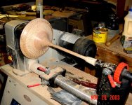
I got lucky and only had to make one prototype to figure out the best glue up method since Oak is an open-grained PIA to turn.
Here is my finished (turned) valve.
I think ThomasW sent me this same info when I was in the early stages of building my Maelstrom Sonosub and I wanted to do the Power Port thing, but I was going to make mine moveable (up and down) in a vertical port, but I couldn’t get a port at the bottom of the enclosure where it needs to be for the Power Port design to work properly. As ThomasW stated I also found the Power Port to be too difficult, if you read the white paper you will discover that the stem diameter and length as well as the proximity of the valve head to the opening is all interrelated and critical for proper operation. I decided that turning several different valves with different stem diameters was too much trouble for the little gain you get, so I just used the valve idea as a Port Plug and a decorative finial to dress out the top of an ugly Sonotube. CAT makes some custom subs just like what you are describing except without the Power Port, but if your sub will be out in the middle of a room with no wall boundaries close by (like a coffee table sub) then you will be wasting a lot of SPL and you wont be able to tweak it much.
You could just run the ports horizontal so they will fit in the enclosure, also have you modeled the drivers you whish to use in a appropriate size box, if you can keep the velocity down below 18m/s you will have no port noise in even the most extreme conditions. BTW you mentioned a sketch of your design, did you post this, I couldn’t find one.
I got lucky and only had to make one prototype to figure out the best glue up method since Oak is an open-grained PIA to turn.
Here is my finished (turned) valve.
Attachments
KingDaddy
Yes that is similar to what I had in mind. I would not make it one piece, although that is beautiful. I think I would turn the wave guides and connect them. Using the software (see link above), what appears to change tuning the most is changing the connector diameter, thereby changing the annulus area (and tuning) significantly. Seems tuning could be accomplished with a method unconventional. Rather than change port length or "valve" (wave guide) height, fix those parameters and change inside tube diameter. As it is better to start with a long (conventional port) port and tune shorter, it is better to start with a conservatively thin (as opposed to conservatively long) connector (powerport) and wrap it to extend the diameter (ideas on materials please?).
That is my take on the spreadsheet.
My sketch is the written sketch on the first post. If you run the spreadsheet, I preloaded my numbers into it, it requires a 3" dia connector, So PVC would be my choice as 3" dowel rod is pricey, $40 for 3 feet. Fill the PVC with expansion foam to negate any acoustical influence, cut to length.
I'd love to see your whole project, do you have a photo?
My ports, as presently designed, would create about 24 m/s at only 500W. Even at 1000 W they may not be heard as long as the equivalent diameters of the ports is 8", or more, each (see the spreadsheet), but I contend there will still be some compression loss, however minimized, which is the object of the design, minimizing port compression dB loss with the high excursion driver. To really let this driver breath might create a new level of performance, as impractical as this effort may seem to some. It's all about having fun, right?
I am having trouble posting graphics, the file sizes are too big and I can't seem to shrink them enough.
I am having trouble posting graphics, the file sizes are too big and I can't seem to shrink them enough.
masterp2 said:KingDaddy
it is better to start with a conservatively thin (as opposed to conservatively long) connector (power port) and wrap it to extend the diameter (ideas on materials please?).
I'd love to see your whole project, do you have a photo?
Cold heat shrink tape comes to mind it's much thicker than regular tape so it would build up the valve stem easier, this as you mentioned will also change the tuning frequency a bit. 24 m/s could be a problem at least with test tones it will make port noise, I experimented on about 8 different port lengths and diameters and found the 8" to work the best for a 147L tuned to 19Hz, no pipe resonance and no port noise.
Pictures of my project are on this page
http://www.diyaudio.com/forums/showthread.php?s=&threadid=25075
1.5" dia router bits will make a pretty big flare, but unfortunately it's not even close to the flare of the Aeroport. The beginning diameter is 6" and it ends up over 9" in diameter. That's why those specific flares will replace a 8" straight port.
No way I'd do reference level SPL plots. The woofer would blow down the house. The webpage plots are pretty straight forward and represent the actual performance of the driver, the port itself and the EQ used to create the final response plot. They are sine swept Clio nearfield frequency response plots made with a $5000 calibrated microphone.
The only real 'advantage' to using a larger box with the AS-15 design is that it would be slightly more efficient.
Tuning the HE-15 lower than ~18Hz IMO isn't a good idea. It takes EQ to flatten the curve with 18Hz tuning. It would take MUCH more EQ and a TON more power to get any appreciable output using a tuning lower than ~18Hz.
True flared ports create the flare itself slowly. The 6" AeroPort is almost 3 1/2" deep. And remember there is one flare on each end of the port. The dual flares combined with the slow flaring rate cuts down on the air turbulence.
The router bits make a much shallower (less deep) flare. So the flare is less beneficial. But it's certainly better than no flare.
BTW, those BIG router bits are really really dangerous, so be careful. Remove VERY small amounts of material at a time. If one of those big bits bind it can break your wrist!
Yup, I figured the flair on the aeroports was more parabolic. I guess it would be possible to tool the wave guides to match them, but I really am looking forward to a big roundover, never did one that big before. Since that really needs to be a handheld operation, I may need to sport my body armor and a sidearm. 
KingDaddy,
Thank you for the tape suggestion and the link to your project. I will indulge that first thing tomorrow, as I have some guests staying at my house tonight, part of the cast of a traveling play going from church to church.
I am interested to know if you think that the software was accurate in predicting response. It is one of those things about being the first on the block to try something new that requires a big investment of time, the water is a little colder, don't you think? But I remember now that you said you didn't actually use the powerport, hmmm. The water just got even colder.
Anybody tried this?? Besides Matt Polk!
I think you will have a hard time finding anyone who has tried or succeeded implementation of the Polk Power Port, most all of us (I would think) concluded that the trouble to get it to work at all just outweighs the benefit especially when there are easier alternatives to avoiding port noise. Not trying to discourage you, hell I admire someone with gumption, so if you feel intrigued by this way of controlling port velocity then you could be one of the first to really try it out and hopefully report your findings.
I believe Polk used this high tech method to keep the cabinet as small as possible with the lowest feasible Fb, the larger the enclosure the slower the velocity. Did you try modeling a single 8” port, if not give it a try, BTW what drivers are you using?
I believe Polk used this high tech method to keep the cabinet as small as possible with the lowest feasible Fb, the larger the enclosure the slower the velocity. Did you try modeling a single 8” port, if not give it a try, BTW what drivers are you using?
It is a single he-15. I think a single 8" would have the same length problem. 16/18 ratio or 90% as long as the 6's, a little better, and that brings the port length to a tiny 52" length (18 HZ in 200l), heck that's 55l just for the port! Doubt I could load the 90 degree fitting without a crane. Yikes.
Back to dual 6's in a powerport config, 28" each, this should work. Just have to flair, flair, flair.
Loved your maelstrom, all that was needed was an occasional flame coming out from the sides of the valve.
I am assuming that you approached tuning from adjusting the height of the wave guide, in your original plan. What was the volume?
What is the diameter of the wave guide? Can you change the Fb by adjusting it? Is ther an optimum Fb, i.e. a compromise between extension and SPL?
ThomasW, would you elaborate a little why tuning under 18 becomes an EQ/power headache? I've heard you say this before, I'd like to understand it, although I have no desire to go lower.
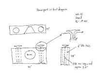
Sofa Table
Here is initial concept with some revision. A picture is way better than a description. This is a simple illustration, I'm planning for it to be a nice piece of furniture, possible with carved legs.
Possible issues:
1. driver clearance to back of cabinet
2. Thinking of a heavy glass table top suspended above the powerports.
3. Proper bracing with large front/back panels, resonance reduction.
Please feel free to critique, I need it.
Attachments
- Status
- This old topic is closed. If you want to reopen this topic, contact a moderator using the "Report Post" button.
- Home
- Loudspeakers
- Multi-Way
- EBS: Powerport application