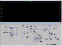
In my search for a discrete phono-stage I fell over this old schematic on Paul Kemble's webpage.
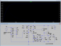
It seems to originate from Wireless World, I wonder if anyone has built this one? The original is for dual 25V supply but I assume it will work for single supply too as shown on the second image.
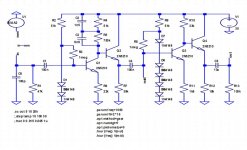
There is no global feedback and bias is controlled by the voltage drop over 2 and 5 diodes respectively. A strange arrangement that needs to be modeled in spice and tested by experiment. The RIAA equalizer is of a passive type across the collector resistance of the first transistor.
If this works it may be an alternative to the Pacific-style jfet phono preamps, since it is based on standard bipolar transistors and not on difficult-to-obtain 2sk170's.
Please give your input and comments, thank you.
Link to schematic, at the middle of the page:http://www.angelfire.com/sd/paulkemble/sound4.html
It seems to originate from Wireless World, I wonder if anyone has built this one? The original is for dual 25V supply but I assume it will work for single supply too as shown on the second image.
There is no global feedback and bias is controlled by the voltage drop over 2 and 5 diodes respectively. A strange arrangement that needs to be modeled in spice and tested by experiment. The RIAA equalizer is of a passive type across the collector resistance of the first transistor.
If this works it may be an alternative to the Pacific-style jfet phono preamps, since it is based on standard bipolar transistors and not on difficult-to-obtain 2sk170's.
Please give your input and comments, thank you.
Link to schematic, at the middle of the page:http://www.angelfire.com/sd/paulkemble/sound4.html
Attachments
DUG is right about the 50V but a friend who built the original was happy with it and I didn't see/hear any issues. One of the simplest and most compact solutions I found and used was the HA12017 (same web page) which, as I mentioned, was comparable to far more complex designs. Currently I'm still happy with a Technics design.
Thank you all for your comments! I don't have 2n5120 but 2SC1815, 2sc815 and 2N3904 are available.
My comments and questions:
@DUG: You are right, if I build it I will use 30 volts and not 50, maybe I need to scale the resistor networks in that case.
@Paul Kemble: Thank you for all the info on your page. I plan not to use opamps but only BJT's for this build. Which Technics design do you use?
@Knutn: Regarding emitter resistor noise, can you please show how to calculate? Would it help to scale the resistors down and increase the current?
@Salas: Alex Nikitin's srpp, do you refer to the Creek preamp? I had a look at it and it may well be an option, thank you for the tip.
From the first simulations in ltspice I believe some component values could be adjusted slightly....
@Salas: Alex Nikitin's srpp, do you refer to the Creek preamp? I had a look at it and it may well be an option, thank you for the tip.
From the first simulations in ltspice I believe some component values could be adjusted slightly....
This "2010" version is designed for DIY and easier to build.
The input JFETs should be a selected pair (J113 or BF244B may be used in that position). R4 value may need to be adjusted for the flattest LF response (using a reverse RIAA network on the input) - it somewhat depends on the BJTs used.
Cheers
Alex
Last edited:
Thank you all for your comments! I don't have 2n5120 but 2SC1815, 2sc815 and 2N3904 are available.
My comments and questions:
@Knutn: Regarding emitter resistor noise, can you please show how to calculate? Would it help to scale the resistors down and increase the current?
From the first simulations in ltspice I believe some component values could be adjusted slightly....
To be honest: I don't like the proposed amplifier. It would be much better to stick to for example the Salas amplifier (http://www.diyaudio.com/forums/analogue-source/129126-simplistic-njfet-riaa.html). I don't think it is that difficult to get the transistors (2SK/LSK170).
And yes, generally it will help to scale down the resistor values, but it all depends on the equivalent noise current for the transistor chosen (but 2N5210 favours low collector current).
This "2010" version is designed for DIY and easier to build.
The input JFETs should be a selected pair (J113 or BF244B may be used in that position). R4 value may need to be adjusted for the flattest LF response (using a reverse RIAA network on the input) - it somewhat depends on the BJTs used.
Cheers
Alex
What is the advantage of using a FET input instead of a bipolar transistor?
Seems to me that the bipolar is a better choice as it has lower noise.
Any comments?
Input equivalent noise has current and voltage elements, with fets the current is significantly reduced so using the equations a higher input noise voltage is 'acceptable' to achieve the same result. Fets can, arguably be faster. Personally I think, for personal use, one that has to decide whether the purpose is to listen to the music or the equipment it is played on.
What is the advantage of using a FET input instead of a bipolar transistor?
Seems to me that the bipolar is a better choice as it has lower noise.
Any comments?
In that circuit you lose the input capacitor coupling because of the FET+BJT cascode is a serious plus. Looks like MM gain level to me so the J113 noise figure should be compatible enough plus the assorted gate stopper and source pin resistors should be smothered for noise contribution by the cartridge's own higher impedance. I would not mate it with a high output MC which has 150-250 Ohm source impedance. Staying with MM cartridges which have high Zo seems adequate. Alex will probably comment and correct any wrong assumptions of course.
In that circuit you lose the input capacitor coupling because of the FET+BJT cascode is a serious plus. Looks like MM gain level to me so the J113 noise figure should be compatible enough plus the assorted gate stopper and source pin resistors should be smothered for noise contribution by the cartridge's own higher impedance. I would not mate it with a high output MC which has 150-250 Ohm source impedance. Staying with MM cartridges which have high Zo seems adequate. Alex will probably comment and correct any wrong assumptions of course.
High output MC cartridges (2-4mV output at 5cm/s) should be OK with this circuit, the gain is about 90 (39dB) at 1kHz. If you need it to work with a "standard" output MC (0.4-0.5mV at 5cm/s) the input JFET should be replaced by 2SK170BL (a matched pair should be used for two channells), R2 = 47 Ohm, R15 replaced by a link, R6 = 1kohm (or another value siutable for a particular cartridge, i.e. 100 Ohm etc), C11 = 1000pF. This will give you about 56dB gain at 1kHz. For MC cartridges with the output of 0.2-0.3mV, a 1000uF electrolytic capacitor should be connected in parallel to R2, boosting the gain up to ~62dB at 1kHz.
Cheers
Alex

 Thank's Alex, Salas and Paul for your explanations!
I simulated the circuit in Ltspice, because i did not understand the clever feedback and how the RIAA network is calculated....
Unfortunately Ltspice did not help me much to understand the design :-/
But i got some interesting figures:
The input noise is 3.3 uV with my MM cartridge model (0.5 Henry, 1k)
The max gain is 64dB at 20 Hz and the THD is relatively high:
0.4% for 5 mV input at 20 Hz
I compard this to a simple OPV preamp from Douglas Self for comparison:
The OPV version has only 46 dB gain and mutch better THD.
The input noise is not bad either for this simple circuit: 3.8uV for an NE5534
I would go for the simpler and cheaper OPV circuit, or do i miss an important advantage of the discrete version?
Last edited:
Its SRPP with the RIAA filter executed inside its loop. You will find many SRPP descriptions in tube articles if you will Google it up, also many projects including such topology in tube projects here in DIYA.
You should use 0.25mV signal for its top gain, 0.5mV for its medium gain, and 5mV for its low gain configuration. Gain and THD should be characterized at 1kHz with the signal anti-RIAA filtered. Having listened to Alex's Creek designs, its not something compatible with a 5532/4 phono stage subjectively, different presentations. You should try both and decide for yourself.
You should use 0.25mV signal for its top gain, 0.5mV for its medium gain, and 5mV for its low gain configuration. Gain and THD should be characterized at 1kHz with the signal anti-RIAA filtered. Having listened to Alex's Creek designs, its not something compatible with a 5532/4 phono stage subjectively, different presentations. You should try both and decide for yourself.
I am concerned that the single supply circuit shown in post#1, may not exhibit wonderful PSRR. A couple of injection pathways for "supply-signals" (aka noise) are shown in red. Might want to build it dual-mono, with two spectacularly good voltage regulators, one per channel.
Attachments
I agree that the design from post #1 will need some good power supply filtering like most other single-ended designs. A good voltage regulator (discrete or IC) will do the job, there are plenty of nice schematics out there. In addition an R-C filter can be added between the first and second stage.
Since noise may be an issue, it could be nice to see a noise calculation/simulation on that one, I am not sure how to do it correctly, please advise?
Regarding the Creek phono, I was actually referring to the old bjt-only version described in this thread:
http://www.diyaudio.com/forums/analogue-source/14904-simple-mm-only-riaa-preamp-2.html
Any comments on this design?
I have not decided which one I will go for, it is still in the design phase, so I guess it will be a project for the winter anyway....
Attachments
Spice simulation
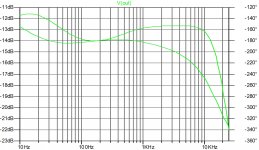
Here is my spice simulation of the original proposal, it is not the most linear response, but it seems to do the job. If we adjust the values of the riaa filter the response may be more accurate. Output is around 225mv @5mv/1khz input and thd is less than 0.01%
Here is my spice simulation of the original proposal, it is not the most linear response, but it seems to do the job. If we adjust the values of the riaa filter the response may be more accurate. Output is around 225mv @5mv/1khz input and thd is less than 0.01%
Attachments
Here is another one I was looking into it recently after a member here made a request to check it out. Was sounding very nice to him but something was amiss. "Olson Mini Phono" he said. I have no other clue. Original simulated had bad RIAA curve so I ironed it out a bit. 34.5dB gain & mostly flat with -1dB @ 30Hz drop was best I could do for it quickly. Could be simulated with an MM cart generator model and some pF Cin Load if you would want to take it further. Or Laplace error comparison RIAA signal instead of the grid anti-RAA filter, whatever.
Attachments
Its SRPP with the RIAA filter executed inside its loop. You will find many SRPP descriptions in tube articles if you will Google it up, also many projects including such topology in tube projects here in DIYA.
You should use 0.25mV signal for its top gain, 0.5mV for its medium gain, and 5mV for its low gain configuration. Gain and THD should be characterized at 1kHz with the signal anti-RIAA filtered. Having listened to Alex's Creek designs, its not something compatible with a 5532/4 phono stage subjectively, different presentations. You should try both and decide for yourself.
Thanks Salas!
I simulated the circuit at 1kHz and THD is now mutch better (0.008%).
Power Supply Rejection (-16dB at 100 Hz) is be a problem, even when using a regulator.
Meantime is see the advantage of a JFet input, as the noise does not depend on the impedance of the cartridge and i learned that there are really good Jfets out there like the BF862
") .
.Do you think that ESD sensitivity is a problem with the JFet?
Greetings,
Udo
- Home
- Source & Line
- Analogue Source
- Discrete phono stage, single supply.